Kenwood TS-890S Operation Manual - Page 18
Terminal Descriptions
 |
View all Kenwood TS-890S manuals
Add to My Manuals
Save this manual to your list of manuals |
Page 18 highlights
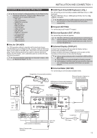
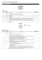
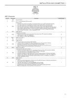
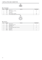
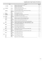
1 INSTALLATION AND CONNECTION Terminal Descriptions . COM Connector Pin No. 1 2 3 4 5 6 7 8 9 Pin Name NC RXD TXD NC GND NC RTS CTS NC Function No connection Sends serial data from this transceiver to RXD on the PC. Receives serial data from TXD on the PC to this transceiver. No connection Signal ground No connection Sends signal from RTS on the PC to this transceiver. If the PC is unable to accept incoming data, an "L" level signal is output from the PC to this transceiver and data will not be sent in this case. Sends signal from this transceiver to CTS on the PC. If this transceiver is unable to accept incoming data, an "L" level signal is output from this transceiver to the PC and input of incoming data will be forbidden. No connection Input/Output - O I - - - I O - (/%ɿ Connect to metal shield. . REMOTE Connector Pin No. 1 2 3 4 5 6 7 Pin Name SPO COM SS MKE BRK ALC LKY Function Speaker out Common terminal of the built-in relay for linear amplifier control PTT input • Sends signal by grounding the SS terminal. Make terminal of the built-in relay for linear amplifier control • The make terminal can be connected to the common terminal during transmission by configuring " Internal Relay Control " (16-14) of the linear amplifier menu. Rated control capacity of relay contact: 2 A/ 30 V DC (resistance load) Maximum allowable voltage of relay contact: 220 V DC, 250 V AC Break terminal of the built-in relay for linear amplifier control • The break terminal can be connected with the common terminal when the latter is not connected to a make terminal. Rated control capacity of relay contact: 2 A/ 30 V DC (resistance load) Maximum allowable voltage of relay contact: 220 V DC, 250 V AC ALC input from the linear amplifier • This is a negative input. The ALC circuit starts to operate from an input of approximately -4 V (which can be changed from the Linear Amplifier menu). Linear amplifier control output • The output logic during transmission can be configured using " Keying Logic " (16-14) of the linear amplifier menu. "Active High": Outputs DC 12 V during transmission. The maximum output current is 100 mA. "Active Low": Switches to the "L" level (GND and short) during transmission. When an external bias is applied while receiving is in progress, the signal switches to the "H" level. Voltage and current not higher than DC 50 V and 100 mA respectively can be controlled. Input/Output O I/O I I/O I/O I O 1-6
-
 1
1 -
2
-
3
-
4
-
5
-
6
-
7
-
8
-
9
-
10
-
11
-
12
-
 13
13 -
 14
14 -
 15
15 -
 16
16 -
 17
17 -
 18
18 -
 19
19 -
 20
20 -
 21
21 -
 22
22 -
 23
23 -
24
-
25
-
26
-
27
-
28
-
29
-
30
-
31
-
32
-
33
-
34
-
35
-
36
-
37
-
38
-
39
-
40
-
41
-
42
-
43
-
44
-
45
-
46
-
47
-
48
-
49
-
50
-
51
-
52
-
53
-
54
-
55
-
56
-
57
-
58
-
59
-
60
-
61
-
62
-
63
-
64
-
65
-
66
-
67
-
68
-
69
-
70
-
71
-
72
-
73
-
74
-
75
-
76
-
77
-
78
-
79
-
80
-
81
-
82
-
83
-
84
-
85
-
86
-
87
-
88
-
89
-
90
-
91
-
92
-
93
-
94
-
95
-
96
-
97
-
98
-
99
-
100
-
101
-
102
-
103
-
104
-
105
-
106
-
107
-
108
-
109
-
110
-
111
-
112
-
113
-
114
-
115
-
116
-
117
-
118
-
119
-
120
-
121
-
122
-
123
-
124
-
125
-
126
-
127
-
128
-
129
-
130
-
131
-
132
-
133
-
134
-
135
-
136
-
137
-
138
-
139
-
140
-
141
-
142
-
143
-
144
-
145
-
146
-
147
-
148
-
149
-
150
-
151
-
152
-
153
-
154
-
155
-
156
-
157
-
158
-
159
-
160
-
161
-
162
-
163
-
164
-
165
-
166
-
167
-
168
-
169
-
170
-
171
-
172
-
173
-
174
-
175
-
176
-
177
-
178
-
179
-
180
-
181
-
182
-
183
-
184
-
185
-
186
-
187
-
188
-
189
-
190
-
191
-
192
-
193
-
194
-
195
-
196
 |
 |
