Kenwood TS-990S Operation Manual - Page 265
Switching The Com Connector Pin Arrangement, Acc 2, Adv.], Advanced Menu, Select], Menu]
 |
View all Kenwood TS-990S manuals
Add to My Manuals
Save this manual to your list of manuals |
Page 265 highlights
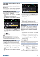
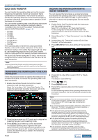
SWITCHING THE COM CONNECTOR PIN ARRANGEMENT You can configure the RTS/CTS terminals of the COM connector on the rear panel allowing it to function in the same manner as the MSQ/PKS terminals of the ACC 2 connector. '
-
 1
1 -
2
-
3
-
4
-
5
-
6
-
7
-
8
-
9
-
10
-
11
-
12
-
13
-
14
-
15
-
16
-
17
-
18
-
19
-
20
-
21
-
22
-
23
-
24
-
25
-
26
-
27
-
28
-
29
-
30
-
31
-
32
-
33
-
34
-
35
-
36
-
37
-
38
-
39
-
40
-
41
-
42
-
43
-
44
-
45
-
46
-
47
-
48
-
49
-
50
-
51
-
52
-
53
-
54
-
55
-
56
-
57
-
58
-
59
-
60
-
61
-
62
-
63
-
64
-
65
-
66
-
67
-
68
-
69
-
70
-
71
-
72
-
73
-
74
-
75
-
76
-
77
-
78
-
79
-
80
-
81
-
82
-
83
-
84
-
85
-
86
-
87
-
88
-
89
-
90
-
91
-
92
-
93
-
94
-
95
-
96
-
97
-
98
-
99
-
100
-
101
-
102
-
103
-
104
-
105
-
106
-
107
-
108
-
109
-
110
-
111
-
112
-
113
-
114
-
115
-
116
-
117
-
118
-
119
-
120
-
121
-
122
-
123
-
124
-
125
-
126
-
127
-
128
-
129
-
130
-
131
-
132
-
133
-
134
-
135
-
136
-
137
-
138
-
139
-
140
-
141
-
142
-
143
-
144
-
145
-
146
-
147
-
148
-
149
-
150
-
151
-
152
-
153
-
154
-
155
-
156
-
157
-
158
-
159
-
160
-
161
-
162
-
163
-
164
-
165
-
166
-
167
-
168
-
169
-
170
-
171
-
172
-
173
-
174
-
175
-
176
-
177
-
178
-
179
-
180
-
181
-
182
-
183
-
184
-
185
-
186
-
187
-
188
-
189
-
190
-
191
-
192
-
193
-
194
-
195
-
196
-
197
-
198
-
199
-
200
-
201
-
202
-
203
-
204
-
205
-
206
-
207
-
208
-
209
-
210
-
211
-
212
-
213
-
214
-
215
-
216
-
217
-
218
-
219
-
220
-
221
-
222
-
223
-
224
-
225
-
226
-
227
-
228
-
229
-
230
-
231
-
232
-
233
-
234
-
235
-
236
-
237
-
238
-
239
-
240
-
241
-
242
-
243
-
244
-
245
-
246
-
247
-
248
-
249
-
250
-
251
-
252
-
253
-
254
-
255
-
256
-
257
-
258
-
259
-
 260
260 -
 261
261 -
 262
262 -
 263
263 -
 264
264 -
 265
265 -
 266
266 -
 267
267 -
 268
268 -
 269
269 -
 270
270 -
271
-
272
-
273
-
274
-
275
-
276
-
277
-
278
-
279
-
280
-
281
-
282
-
283
-
284
-
285
-
286
-
287
-
288
-
289
-
290
-
291
-
292
-
293
-
294
-
295
-
296
-
297
-
298
-
299
-
300
 |
 |
USEFUL FUNCTIONS 16
16-25
Index
Contents
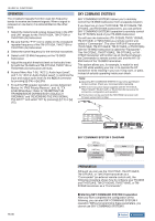
SWITCHING THE COM CONNECTOR PIN
ARRANGEMENT
You can configure the RTS/CTS terminals of the
COM
connector on the rear panel allowing it to function in the
same manner as the MSQ/PKS terminals of the
ACC 2
connector.
[
]
[F1]~[F7]
[MENU]
F[ADV.]
1
Press
[ADV.]
(F) from the
Menu
screen to open the
Advanced Menu
screen.
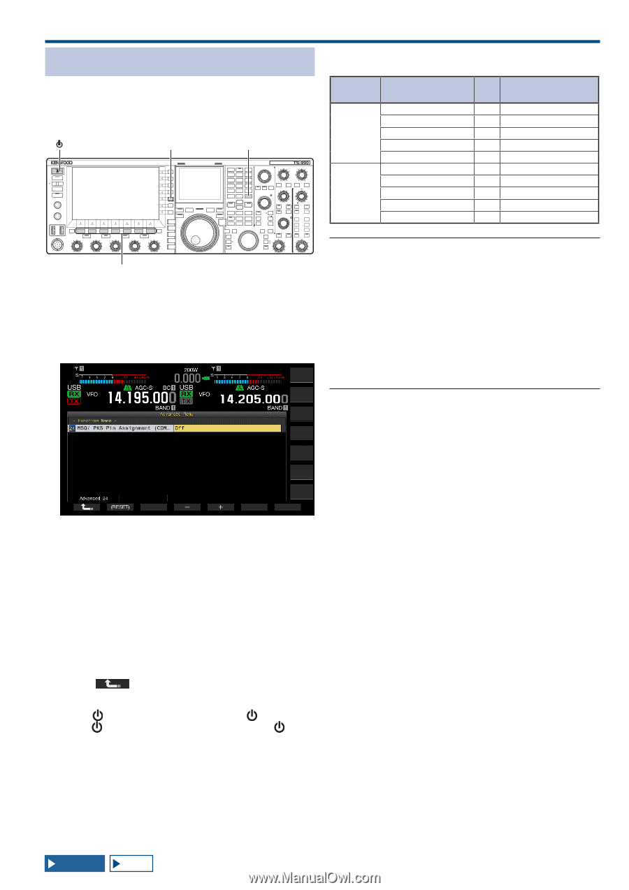
2
Access Menu 24, "MSQ/PKS Pin Assignment (COM
Connector)".
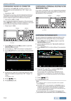
3
Press
[SELECT]
(F4) to allow editing of the parameter
box.
4
Press
[-]
(F4) or
[+]
(F5) to select "On" or "Off" to
determine the pin behavior.
The default is "Off".
Off: The COM connector is normal (CTS/RTS mode).
The
COM
connector processes the RTS signal and CTS
signal.
On: The COM connector is in MSQ/PKS mode.
The signals on the RTS and CTS pins of the
COM
connector
are replaced with the MSQ and PKS signals, respectively.
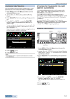
A message confirming the
COM
connector behavior appears.
5
Press
[OK]
(F4).
6
Press
[
]
(F1).
7
Press
[MENU]
to exit.
8
Press
[
]
to turn the transceiver power (
) OFF, then
press
[
]
again to turn the transceiver power (
) ON.
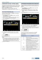
The output signals for each configuration behaves as
follows:
COM Terminal on the
rear panel
PC
CTS/ RTS
(Default)
TxD
→
RxD
RxD
←
TxD
RTS
→
CTS
CTS
←
RTS
GND
GND
MSQ/ PKS
No function
→
RxD
No function
←
TxD
MSQ
→
CTS
PKS
←
RTS
GND
GND
Note:
◆
The revised configurations cannot be enabled until the transceiver
is restarted.
◆
If "On" is configured for the MSQ/PKS Pin Assignment, you cannot
control the transceiver using the ARCP-990 and ARHP-990 or by
PC commands sent via the
COM
connector.
◆
If "Off" is configured for the MSQ/PKS Pin Assignment, the
transceiver transmits when the PKS pin of the
ACC 2
connector is
shorted to GND.
◆
The I/O level of the audio varies depending on the sound device
connected. If the audio I/O level does not match the transceiver,
use Menus 7-06, 7-10, and 7-11 to change the audio I/O level on
the
ACC 2
connector.
{page 16-20}
◆
The squelch signal of the sub band cannot be transferred.