Kenwood TS-990S Operation Manual - Page 271
Ts-990s + Th-d72a/e, Tm-d710ga/e, Tm-d710a/e Or Tm-d700a (g) (transporter) Configuration
 |
View all Kenwood TS-990S manuals
Add to My Manuals
Save this manual to your list of manuals |
Page 271 highlights
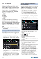
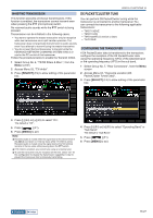
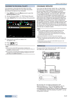
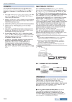
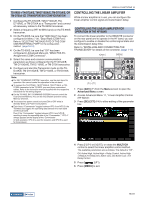
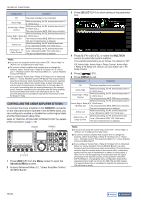
USEFUL FUNCTIONS 16 TS-990S + TH-D72A/E, TM-D710GA/E, TM-D710A/E, or TM-D700A (G) (Transporter) Configuration 1 Configure the TH-D72A/E, TM-D710GA/E, TMD710A/E, or TM-D700A as a "Transporter" and connect all necessary cables to the TS-990S transceiver. 2 Select a frequency (HF/ 50 MHz band) on the TS-990S transceiver. 3 On the TS-990S, be sure that "9600 [bps]" has been configured in Menu 7-00, "Baud Rate (COM Port)". Refer to "SELECTING THE BAUD RATE OF THE COM/ USB (REAR PANEL) PORT" for the configuration method. {page 16-10} 4 On the TS-990S, be sure that "Off" has been configured in Advanced Menu 24, "MSQ/ PKS Pin Assignment (COM Connector)". 5 Select the same and common communication parameters as those configured for the TH-D72A/E, TM-D710GA/E, TM-D710A/E, or TM-D700 transceiver. 6 Configure and start the Transporter mode on the THD72A/E, TM-D710GA/E, TM-D710A/E, or TM-D700A transceiver. Note: ◆◆For SKY COMMAND SYSTEM II operation, use the main band for operation. You cannot control the operation in the sub band. ◆◆To connect the TH-D72A/E, TM-D710GA/E, TM-D710A/E, or TMD700A transceiver to the TS-990S, you need three customized cables. Refer to the instruction manual supplied with the respective transceiver for the wiring diagram. ◆◆On the TS-990S, SKY COMMAND SYSTEM II cannot control the Dual Channel Memory.You can do only Simplex operation using Memory Channel. ◆◆The transceiver power cannot be turned ON or OFF while in Standby State Low Power Consumption. ◆◆Each time a "Commander" toggles between VFO A and VFO B, the TS-990S also toggles the operating data between the main band and the sub band. Even if the "Commander" toggles between VFO A and VFO B resulting to swap the operating data of the "Commander", "VFO A" always appears on the display of the "Commander". In Split operation, VFO A is used for reception and VFO B is used for transmission. CONTROLLING THE LINEAR AMPLIFIER While a linear amplifier is in use, you can configure the linear amplifier control signal and transmission delay. CONTROLLING THE LINEAR AMPLIFIER FOR OPERATION IN THE HF BAND To connect the linear amplifier to the REMOTE connector on the rear panel and to operate in the HF band, you can configure to enable or disable the control signal state and the transmission delay time. Refer to "INSTALLING AND CONNECTING THE TRANSCEIVER" for details of the connector. {page 1-10} '
-
 1
1 -
2
-
3
-
4
-
5
-
6
-
7
-
8
-
9
-
10
-
11
-
12
-
13
-
14
-
15
-
16
-
17
-
18
-
19
-
20
-
21
-
22
-
23
-
24
-
25
-
26
-
27
-
28
-
29
-
30
-
31
-
32
-
33
-
34
-
35
-
36
-
37
-
38
-
39
-
40
-
41
-
42
-
43
-
44
-
45
-
46
-
47
-
48
-
49
-
50
-
51
-
52
-
53
-
54
-
55
-
56
-
57
-
58
-
59
-
60
-
61
-
62
-
63
-
64
-
65
-
66
-
67
-
68
-
69
-
70
-
71
-
72
-
73
-
74
-
75
-
76
-
77
-
78
-
79
-
80
-
81
-
82
-
83
-
84
-
85
-
86
-
87
-
88
-
89
-
90
-
91
-
92
-
93
-
94
-
95
-
96
-
97
-
98
-
99
-
100
-
101
-
102
-
103
-
104
-
105
-
106
-
107
-
108
-
109
-
110
-
111
-
112
-
113
-
114
-
115
-
116
-
117
-
118
-
119
-
120
-
121
-
122
-
123
-
124
-
125
-
126
-
127
-
128
-
129
-
130
-
131
-
132
-
133
-
134
-
135
-
136
-
137
-
138
-
139
-
140
-
141
-
142
-
143
-
144
-
145
-
146
-
147
-
148
-
149
-
150
-
151
-
152
-
153
-
154
-
155
-
156
-
157
-
158
-
159
-
160
-
161
-
162
-
163
-
164
-
165
-
166
-
167
-
168
-
169
-
170
-
171
-
172
-
173
-
174
-
175
-
176
-
177
-
178
-
179
-
180
-
181
-
182
-
183
-
184
-
185
-
186
-
187
-
188
-
189
-
190
-
191
-
192
-
193
-
194
-
195
-
196
-
197
-
198
-
199
-
200
-
201
-
202
-
203
-
204
-
205
-
206
-
207
-
208
-
209
-
210
-
211
-
212
-
213
-
214
-
215
-
216
-
217
-
218
-
219
-
220
-
221
-
222
-
223
-
224
-
225
-
226
-
227
-
228
-
229
-
230
-
231
-
232
-
233
-
234
-
235
-
236
-
237
-
238
-
239
-
240
-
241
-
242
-
243
-
244
-
245
-
246
-
247
-
248
-
249
-
250
-
251
-
252
-
253
-
254
-
255
-
256
-
257
-
258
-
259
-
260
-
261
-
262
-
263
-
264
-
265
-
 266
266 -
 267
267 -
 268
268 -
 269
269 -
 270
270 -
 271
271 -
 272
272 -
 273
273 -
 274
274 -
 275
275 -
 276
276 -
277
-
278
-
279
-
280
-
281
-
282
-
283
-
284
-
285
-
286
-
287
-
288
-
289
-
290
-
291
-
292
-
293
-
294
-
295
-
296
-
297
-
298
-
299
-
300
 |
 |