Kenwood TS-990S Operation Manual - Page 273
Operating The Transceiver As An Exciter Of The Transverter
 |
View all Kenwood TS-990S manuals
Add to My Manuals
Save this manual to your list of manuals |
Page 273 highlights
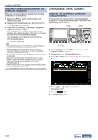
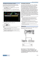
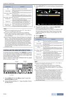
USEFUL FUNCTIONS 16 OPERATING THE TRANSCEIVER AS AN EXCITER OF THE TRANSVERTER This is a convenient function when this transceiver is used coupled with a transverter which can convert the operating frequency of this transceiver to another frequency. Refer to the instruction manual supplied with the transverter for details on how to connect to the transverter. Note: ◆◆If you use a transverter, some functions of the transceiver cannot be used. PRECAUTION: ◆◆Turn the main power switch (I/O) of the transceiver and transverter OFF, then connect the transceiver to the transverter. Be sure that the transceiver is properly connected to the transverter, and then turn the main power switch (I/O) of the transceiver and transverter ON. TRANSMIT POWER REDUCTION WHILE THE TRANSVERTER IS ENABLED If the transverter is capable of 5 W or more RF input level and if a signal exceeding 5 W is entered from the ANT connector to the transverter, you need to select "Off" (do not fix the transmit power to 5 W) for the transmit power down while the transverter is in operation. ' CONNECTING THE TRANSVERTER TO THE Transceiver There are two methods to connect the transceiver to the transverter: Connection via the ANT connector (TX and RX, the fixed 5 W transmit power), and connection via the RX IN connector (RX input) and DRV connector (Drive output). Either of the connections can change the displayed frequency of the transceiver to the operating frequency display of the transverter. If a signal exceeding 5 W is entered from the ANT connector to the transverter, you must also select "Off" in Advanced Menu 08, "TX Power Down with Transverter Enabled", to disable the capability to limit the transmit power to 5 W. 1 Press [ADV.] (F) from the Menu screen to open the Advanced Menu screen. 2 Access Advanced Menu 08, "TX Power Down with Transverter Enabled". 3 Press [SELECT] (F4) to allow editing of the parameter box. ■ To connect to the RX IN and DRV connectors 1 Connect the transverter to the RX IN and DRV connectors. 2 Press [RX IN] to enable the reception via the RX IN connector. " " appears on the main screen. 3 Press [DRV] to enable the transmission via the DRV connector. The "DRV" LED lights green. ■ To connect to the ANT connector 1 Connect the transverter to the ANT connector. 2 Press [RX IN] to disable the reception via the RX IN connector. " " appears on the main screen. 3 Press [DRV] to disable the transmission via the DRV connector. The "DRV" LED turns Off. Note: ◆◆Selecting the RX IN and DRV connectors disable transmission and reception using the ANT connector. 4 Press [-] (F4) or [+] (F5) to select "Off". The default is "On". 5 Press [ ] (F1). 6 Press [MENU] to exit. PRECAUTION: ◆◆If "Off" is selected for Advanced Menu 08, "TX Power Down with Transverter Enabled", a maximum of 200 W electrical power is supplied to the device connected to the ANT connector. This may cause the connected device to be damaged or fail. Contents Index 16-33
-
 1
1 -
2
-
3
-
4
-
5
-
6
-
7
-
8
-
9
-
10
-
11
-
12
-
13
-
14
-
15
-
16
-
17
-
18
-
19
-
20
-
21
-
22
-
23
-
24
-
25
-
26
-
27
-
28
-
29
-
30
-
31
-
32
-
33
-
34
-
35
-
36
-
37
-
38
-
39
-
40
-
41
-
42
-
43
-
44
-
45
-
46
-
47
-
48
-
49
-
50
-
51
-
52
-
53
-
54
-
55
-
56
-
57
-
58
-
59
-
60
-
61
-
62
-
63
-
64
-
65
-
66
-
67
-
68
-
69
-
70
-
71
-
72
-
73
-
74
-
75
-
76
-
77
-
78
-
79
-
80
-
81
-
82
-
83
-
84
-
85
-
86
-
87
-
88
-
89
-
90
-
91
-
92
-
93
-
94
-
95
-
96
-
97
-
98
-
99
-
100
-
101
-
102
-
103
-
104
-
105
-
106
-
107
-
108
-
109
-
110
-
111
-
112
-
113
-
114
-
115
-
116
-
117
-
118
-
119
-
120
-
121
-
122
-
123
-
124
-
125
-
126
-
127
-
128
-
129
-
130
-
131
-
132
-
133
-
134
-
135
-
136
-
137
-
138
-
139
-
140
-
141
-
142
-
143
-
144
-
145
-
146
-
147
-
148
-
149
-
150
-
151
-
152
-
153
-
154
-
155
-
156
-
157
-
158
-
159
-
160
-
161
-
162
-
163
-
164
-
165
-
166
-
167
-
168
-
169
-
170
-
171
-
172
-
173
-
174
-
175
-
176
-
177
-
178
-
179
-
180
-
181
-
182
-
183
-
184
-
185
-
186
-
187
-
188
-
189
-
190
-
191
-
192
-
193
-
194
-
195
-
196
-
197
-
198
-
199
-
200
-
201
-
202
-
203
-
204
-
205
-
206
-
207
-
208
-
209
-
210
-
211
-
212
-
213
-
214
-
215
-
216
-
217
-
218
-
219
-
220
-
221
-
222
-
223
-
224
-
225
-
226
-
227
-
228
-
229
-
230
-
231
-
232
-
233
-
234
-
235
-
236
-
237
-
238
-
239
-
240
-
241
-
242
-
243
-
244
-
245
-
246
-
247
-
248
-
249
-
250
-
251
-
252
-
253
-
254
-
255
-
256
-
257
-
258
-
259
-
260
-
261
-
262
-
263
-
264
-
265
-
266
-
267
-
 268
268 -
 269
269 -
 270
270 -
 271
271 -
 272
272 -
 273
273 -
 274
274 -
 275
275 -
 276
276 -
 277
277 -
 278
278 -
279
-
280
-
281
-
282
-
283
-
284
-
285
-
286
-
287
-
288
-
289
-
290
-
291
-
292
-
293
-
294
-
295
-
296
-
297
-
298
-
299
-
300
 |
 |
