Kenwood VR-5700 User Manual 1
Kenwood VR-5700 Manual
 |
View all Kenwood VR-5700 manuals
Add to My Manuals
Save this manual to your list of manuals |
Kenwood VR-5700 manual content summary:
- Kenwood VR-5700 | User Manual 1 - Page 1
i - Kenwood VR-5700 | User Manual 1 - Page 2
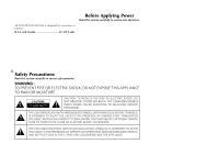
VR-5700/VR-5090/VR-5080 is designed for operation as follows. U.S.A. and Canada AC 120 V only Before Applying Power Read EQUILATERAL TRIANGLE IS INTENDED TO ALERT THE USER TO THE PRESENCE OF IMPORTANT OPERATING AND MAINTENANCE (SERVICING) INSTRUCTIONS IN THE LITERATURE ACCOMPANYING THE APPLIANCE. - Kenwood VR-5700 | User Manual 1 - Page 3
Connecting and Setting Up Your New Kenwood Audio-Video Receiver Welcome to the Connection and Setup Guide for your new Kenwood audio-video receiver. This manual covers three models. The VR-5700/VR-5090/VR-5080 offers 3 kinds of 5.1-channel digital surround sound decoding: • Dolby Digital, for the - Kenwood VR-5700 | User Manual 1 - Page 4
this manual. All other products named are trademarks of their respective companies. As an ENERGY STAR® Partner, Kenwood Corporation receiver is damaged or fails to operate, notify your dealer immediately. If your receiver was shipped to you directly, notify your shipper immediately. Kenwood - Kenwood VR-5700 | User Manual 1 - Page 5
What if I Have an Amplifier 8 Connecting Your TV 10 To Connect a TV What if I Want to Watch TV without Turning on the Receiver? Table of Contents To Connect a Kenwood 200-Disc CD Changer To Connect Any Other Primary CD Player or Changer To Connect a Secondary CD Player Connecting Your DVD Player - Kenwood VR-5700 | User Manual 1 - Page 6
a Kenwood IR-9991 IR Transceiver To connect any other IR Receiver To turn the VR-5700, VR-5090 or VR-5080's RF Receiver off To turn the VR-5700, VR-5090 or VR-5080's RF Receiver back on To Connect IR Repeaters Chapter Five: Warnings and Specifications 50 Warnings VR-5700 Specifications VR-5090/VR - Kenwood VR-5700 | User Manual 1 - Page 7
Your Devices Chapter One: Connecting Your Devices Welcome to the Kenwood VR-5700/ VR-5090/VR-5080 Connection and Setup Guide. This chapter guides you through connecting your home entertainment devices to your new Kenwood audio-video receiver. Once all your devices are connected, you can set up - Kenwood VR-5700 | User Manual 1 - Page 8
Connections Chapter One : Connecting Your Devices The following diagram shows the entire back of the VR-5700/VR-5090/VR-5080. Zone B pre out jacks Pre out jacks System control jacks Supplemental infrared receiver and sensor jacks, RELAY CONTROL jack and TV ON/OFF SENSOR jack RF remote antenna - Kenwood VR-5700 | User Manual 1 - Page 9
Your Devices Jack Set Device PHONO CD1 MD/TAPE1 CD2/TAPE2 MONITOR CD-R MONITOR OUT (TV on Remote Control unit) VIDEO1 VIDEO2 VIDEO3 ( ) VIDEO4 VR-5700/ VR-5090 only DVD Use this table and the diagram on the preceding page to plan your connections before you make them, or use it to - Kenwood VR-5700 | User Manual 1 - Page 10
Connections Chapter One : Connecting Your Devices R FRONT Connecting Your Speakers R SURROUND L SURROUND CENTER L FRONT IR RECEIVER IN IR REPEATER OUT/ IR RECEIVER IR OUT DVD CONTROL IN LCD SL16 TEXT SYSTEM CONTROL RF REMOTE ANTENNA 4 VIDEO R L SUB WOOFER CENTER R SURROUND BACK L R - Kenwood VR-5700 | User Manual 1 - Page 11
and negative wires on the LEFT FRONT speaker. To Connect Front and Surround Sound Speakers: To listen to the full surround sound that this receiver can put out, connect front speakers, center, left surround, and right surround speakers. To do so: For the connections of the subwoofer and surround - Kenwood VR-5700 | User Manual 1 - Page 12
Speakers, continued R SURROUND BACK L SURROUND BACK Power Amp. 6 IR RECEIVER IN IR REPEATER OUT/ IR RECEIVER IR OUT DVD CONTROL IN LCD SL16 TEXT SYSTEM CONTROL RF REMOTE ANTENNA VIDEO MAX. A FRONT SPEAKERS B (6-16Ω) R L CENTER SUBWOOFER The figure shows an example for the VR-5700. - Kenwood VR-5700 | User Manual 1 - Page 13
Have a Powered Subwoofer? Simply connect the subwoofer's audio cable to the receiver's SUBWOOFER PRE OUT jack as shown to the left. To Connect Surround back speakers: 1. Using RCA audio cables (not supplied), connect the receiver's SURROUND BACK PRE OUT jacks to the 2- channel power amplifiers' - Kenwood VR-5700 | User Manual 1 - Page 14
Devices What if I Have an Amplifier? R FRONT Power Amp. CENTER Power Amp. L FRONT The figure shows an example for the VR-5700. IR RECEIVER IN IR REPEATER OUT/ IR RECEIVER IR OUT DVD CONTROL IN LCD SL16 TEXT SYSTEM CONTROL RF REMOTE ANTENNA 8 VIDEO R L SUB WOOFER CENTER R SURROUND BACK - Kenwood VR-5700 | User Manual 1 - Page 15
of the channels instead of the receiver's built-in amplifiers. Do not plug in the amplifiers or the receiver to AC power until all connections supplemental power amplifiers: 1. Using RCA audio cables (not supplied), connect the receiver's PRE OUT jacks to the amplifiers' input jacks as shown to the - Kenwood VR-5700 | User Manual 1 - Page 16
Chapter One : Connecting Your Devices Connecting Your TV 10 COMPONENT VIDEO IN IR RECEIVER IN IR REPEATER OUT/ IR RECEIVER IR OUT DVD CONTROL IN LCD SL16 TEXT SYSTEM CONTROL VIDEO R L SUB RF REMOT ANTENN A The figure shows an example for the VR-5700. S-VIDEO IN COMPOSITE VIDEO IN - Kenwood VR-5700 | User Manual 1 - Page 17
receiver or devices to AC power until you have connected all your devices. This section focuses on the connections from your TV to the VR-5700/VR-5090/VR-5080. Please refer to your TV's instructions Output" on page 13. To Connect a TV: 1. Review the information under "Before You Begin" on page 1. It - Kenwood VR-5700 | User Manual 1 - Page 18
or Satellite Tuner 12 COMPONENT VIDEO OUT IR RECEIVER IN IR REPEATER OUT/ IR RECEIVER IR OUT DVD CONTROL IN LCD SL16 TEXT CD-R PLAY IN CD1 VIDEO 2 CENTER SUBWOOFER VIDEO 3 OPTICAL COAXIAL DIGITAL IN For VR-5080 DC12V 20mA REMOTE A FM 75Ω AM GND ANTENNA RF REMOTE ANTENNA CENTER SPEAKER - Kenwood VR-5700 | User Manual 1 - Page 19
receiver or devices to AC power until you have connected all your devices. This section focuses on the connections from your cable or satellite tuner to the VR-5700/VR-5090/VR-5080. Please refer to your tuner's instructions Connect a Satellite Tuner: 1. Review the information under "Before You Begin - Kenwood VR-5700 | User Manual 1 - Page 20
Connecting Your Devices Connecting Your VCR(s) 14 S-VIDEO IN S-VIDEO OUT IR RECEIVER IN IR REPEATER OUT/ IR RECEIVER IR OUT DVD CONTROL IN LCD SL16 TEXT SYSTEM CONTROL VIDEO R L L A FRONT SPEAKERS (6-16Ω) The figure shows an example for the VR-5700. VIDEO OUT VIDEO IN AUDIO OUT AUDIO IN - Kenwood VR-5700 | User Manual 1 - Page 21
receiver to AC power until you have connected all your devices. This section focuses on the connections from your VCR to the VR-5700/VR-5090/VR-5080. Please refer to your VCR's instructions of the VCR. To Connect a Secondary VCR: 1. Review the information under "Before You Begin" on page 1. It - Kenwood VR-5700 | User Manual 1 - Page 22
$ › DIGITAL OUT - OPTICAL or COAXIAL IR RECEIVER IN IR REPEATER OUT/ IR RECEIVER IR OUT DVD CONTROL IN LCD SL16 TEXT SYSTEM CONTROL SUBWOOFER For VR-5080 (DIGITAL OUT - OPTICAL only) OUTPUT A (CD1) OUTPUT B (CD2)* COMMUNICATION CABLE - KENWOOD ONLY SYSTEM CONTROL CABLE - KENWOOD ONLY DC12V - Kenwood VR-5700 | User Manual 1 - Page 23
CD Player, continued Do not plug in the receiver to AC power until you have connected all your devices. This section focuses on the connections from your 200-Disc CD Changer to the VR-5700/VR-5090/VR-5080. Please refer to your changer's instructions for more detail about its connection jacks and - Kenwood VR-5700 | User Manual 1 - Page 24
Connections Chapter One : Connecting Your Devices Connecting Your DVD Player 18 3 8 7 4¢ DIGITAL OUT - OPTICAL or COAXIAL IR RECEIVER IN IR REPEATER OUT/ IR RECEIVER IR OUT DVD CONTROL IN LCD SL16 TEXT SYSTEM CONTROL Remove protective cap before connecting. VIDEO R L SUB WOOFER CENTER - Kenwood VR-5700 | User Manual 1 - Page 25
receiver to AC power until you have connected all your devices. This section focuses on the connections from your DVD player to the VR-5700/VR-5090/VR-5080. Please refer to your DVD player's instructions one for optical connection. Your DVD player supports one or the other of these connection methods - Kenwood VR-5700 | User Manual 1 - Page 26
Your CD-R Recorder 20 DIGITAL RECORD IN - COAXIAL (VR-5700/VR-5090 only) or OPTICAL Remove protective cap before connecting. VIDEO CR PLAY IN MONITOR OUT DVD FRONT DVD/ 6CH INPUT SURROUND IR RECEIVER IN IR REPEATER OUT/ IR RECEIVER IR OUT DVD CONTROL IN LCD DC12V IR OUT LCD 20mA REMOTE - Kenwood VR-5700 | User Manual 1 - Page 27
the VR-5700/VR-5090/VR-5080. Please refer to IN jacks to the receiver's CD-R REC OUT jacks, as shown to the left. your CD-R recorder instructions for for optical connection. Your The VR-5080 is not equipped with the digital input jack for CD-R recorder. CD-R recorder supports one or the other of - Kenwood VR-5700 | User Manual 1 - Page 28
PLAY IN MONITOR OUT DVD FRONT DVD/ 6CH INPUT SURROUND IR RECEIVER IN IR REPEATER OUT/ IR RECEIVER IR OUT DVD CONTROL IN LCD DC12V IR OUT LCD 20mA REMOTE (VR-5700/VR-5090 only) The figure shows an example for the VR-5700. RECORD IN (ANALOG) PLAY OUT (ANALOG) SYSTEM CONTROL CABLE - KENWOOD ONLY - Kenwood VR-5700 | User Manual 1 - Page 29
, continued Do not plug in the receiver to AC power until you have connected all your devices. This section focuses on the connections from your MD recorder or tape deck to the VR-5700/VR-5090/VR-5080. Please refer to your MD recorder or tape deck's instructions for more detail about its connection - Kenwood VR-5700 | User Manual 1 - Page 30
Your Devices Connecting Your Secondary CD Player or Tape Deck 24 IR RECEIVER IN IR REPEATER OUT/ IR RECEIVER IR OUT DVD CONTROL IN LCD SL16 TEXT SYSTEM CONTROL VIDEO R L A FRONT SPEAKERS B (6-16Ω) The figure shows an example for the VR-5700. TAPE RECORD IN CD OUTPUT OR TAPE PLAY OUT - Kenwood VR-5700 | User Manual 1 - Page 31
receiver to AC power until you have connected all your devices. This section focuses on the connections from your CD player or tape deck to the VR-5700/VR-5090/VR-5080. Please refer to your CD player or tape deck's instructions second CD player, even if it supports system control. 2. Go to "Noting - Kenwood VR-5700 | User Manual 1 - Page 32
INPUT 4 OPTICAL COAXIAL PR/CR MONITOR OUT SURROUND CD1 VIDEO 2 DIGITAL IN VIDEO 3 CENTER SUBWOOFER OPTICAL COAXIAL DIGITAL IN For VR-5080 IR RECEIVER IN IR REPEATER OUT/ IR RECEIVER IR OUT DVD CONTROL IN LCD DC12V IR OUT LCD 20mA REMOTE B R AUDIO L PHONO CD1 REC OUT MD/ TAPE1 PLAY - Kenwood VR-5700 | User Manual 1 - Page 33
all your devices. You must purchase an RF Demodulator (such as the Kenwood DEM-9991D available from one of our parts distributors) if you plan to operate a player with a Dolby Digital (AC-3) RF output with this receiver. These instructions describe how to connect a laser disc player with an AC-3 RF - Kenwood VR-5700 | User Manual 1 - Page 34
Output) 28 DIGITAL OUT OPTICAL or COAXIAL IR RECEIVER IN IR REPEATER OUT/ IR RECEIVER IR OUT DVD CONTROL IN LCD SL16 TEXT SYSTEM PR/CR DIGITAL IN CD1 VIDEO 2 VIDEO 3 OPTICAL COAXIAL DIGITAL IN For VR-5080 PLAY IN MONITOR OUT DVD FRONT DVD/ 6CH INPUT SURROUND CENTER SUBWOOFER DC12V - Kenwood VR-5700 | User Manual 1 - Page 35
digital jack to the appropriate digital jack on the receiver as shown to the left. Your laser disc player supports only one of the digital connection methods-do not connect both. (The optical digital input jacks are available only on the VR-5700/VR-5090) 5. Go to "Noting Your Devices" on page 3 and - Kenwood VR-5700 | User Manual 1 - Page 36
AUDIO OUT Do not plug in the receiver to AC power until you have connected all your devices. This section focuses on the connections from your turntable/ record player to the VR-5700/VR-5090/VR-5080. Please refer to your turntable/record player's instructions for more detail about its connection - Kenwood VR-5700 | User Manual 1 - Page 37
the front of the VR-5700/VR-5090/ VR-5080. Please refer to your camcorder or VCR's instructions for more detail about its connection jacks and capabilities. These instructions describe how to connect a camcorder or VCR quickly and probably temporarily to the front of the receiver. If you want a less - Kenwood VR-5700 | User Manual 1 - Page 38
plug is not connected.) 32 SYSTEM CONTROL cord SYSTEM CONTROL SYSTEM CONTROL Receiver CD Player MD Recorder or Tape Deck Other [SL 16] compatible cables to any device not specified by Kenwood. Using a system control cable with a device that does not support them can damage the device. Make sure - Kenwood VR-5700 | User Manual 1 - Page 39
Remote Control unit for the VR-5700/VR-5090/ VR-5080 communicates with the receiver via RF transmission. To properly receive the RF remote signal, the best reception. FM Outdoor Antenna FM 75Ω AM GND ANTENNA Kenwood recommends a permanently installed outdoor FM antenna for best FM reception. To - Kenwood VR-5700 | User Manual 1 - Page 40
Unit This Remote Control unit can be set up to remote control the receiver as well as most of the devices connected to it. The appearance and backlight off except when necessary. For the backlight, refer to the Users' Guide. The Remote Control unit can be reset in two ways To reset the remote - Kenwood VR-5700 | User Manual 1 - Page 41
to an input is not identified by Remote Control unit, the device name is skipped and not displayed. (VR-5080 only) Although Video4 is displayed in the initial status, the receiver cannot be switched to select Video4. The Video4 display will not appear after the Remote Control unit has been - Kenwood VR-5700 | User Manual 1 - Page 42
There are four areas of speaker setup: • Selecting the Speakers • Balancing the Speaker Volumes • Bass Peak Level • Adjusting the Speaker Distances The receiver must be on and speakers must be connected before you can set up speakers. Speaker Placement An example of installation is shown here. Use - Kenwood VR-5700 | User Manual 1 - Page 43
Chapter Two : Setting Up the Remote Control Unit 8. When the center speaker setting menu appears, select Center Nml/THX, Large or Off in the same way as step 6, then press the Next button. Select Off when no center speaker is connected. (If you select Nml/THX in step 7. "Large" cannot be selected - Kenwood VR-5700 | User Manual 1 - Page 44
Digital and DTS programs can contain up to 10dB more energy than the other channels, which is enough to damage some speakers. The VR-5700/VR-5090/VR-5080 has a bass limiter circuit that keeps the output to your subwoofer (or left & right speakers, if your system doesn't have a subwoofer) within - Kenwood VR-5700 | User Manual 1 - Page 45
code of the device (each device has a remote control identification number matching it) us- ing the or button. • When the device is connected through a Kenwood system control cord, select System. In this case, the remote control signal is sent to the receiver then to the device connected to it. - Kenwood VR-5700 | User Manual 1 - Page 46
Chapter Two : Setting Up the Remote Control Unit Remote Setup 10. Press the AV POWER button. MUSIC AV POWER MOVIE TV SYS.POWER Pressing the AV POWER button causes Remote Control unit to transmit the signal turning on/off the device being set. The device is turned on if the selected setup code - Kenwood VR-5700 | User Manual 1 - Page 47
Chapter Two : Setting Up the Remote Control Unit Remote Setup 1 Press the Exit button (LCD function button 2) to exit from the operation. Press the Clr (clear) button (LCD function button 1) if you want to clear the previously programmed remote control signal and reset to the factory shipment - Kenwood VR-5700 | User Manual 1 - Page 48
Balancing the Speaker Levels with a Sound Level Meter Note: These instructions assume you are using a Radio Shack SPL meter, model 33-2050 CLCD function button 2). 01.IR 02.Surround 03.Contrast HomeFFEnter 9. The receiver's volume control will automatically be set to 0dB and test noise will play - Kenwood VR-5700 | User Manual 1 - Page 49
the area where the re- ceiver is located. 2. Do not position the receiver near metal (such as heat ducts). Metal can absorb RF signals. 3. 12 2 1 The tests for range limits of the Remote Control unit and the Receiver were conducted in open-air distance tests. Ac- tual distance of the signal - Kenwood VR-5700 | User Manual 1 - Page 50
inside the panel door. Make the following preparation for setup on the receiver. Open the panel door by pushing the lower part of the panel door listen mode. See step 6. 3. Press the SET UP button once more. The receiver's display will read CENTER NML/THX. A. If your center speaker is not capable - Kenwood VR-5700 | User Manual 1 - Page 51
SET UP button once more. The receiver's display will read BASS PEAK OFF. Since the LFE (bass effects) channel of Dolby Digital and DTS programs can contain up to 10dB more energy than the other channels, which is enough to damage some speakers. The VR-5700/VR-5090/VR5080 has a bass limiter circuit - Kenwood VR-5700 | User Manual 1 - Page 52
Chapter Four: Setting Up Multiple Zones Chapter Four: Setting Up Multiple Zones The VR-5700/VR-5090/VR-5080 offers dual-zone output and control, which enables you to use a single receiver to control devices and speakers for two zones (rooms). Due to its advanced features and controls, you can play - Kenwood VR-5700 | User Manual 1 - Page 53
two zones to support the different scenarios. Before you read this section, Kenwood recommends reading "Connecting Making Connections Your Speakers" on page 4 of this manual. In addition, this section discusses how to connect a second TV/Monitor and how to connect an IR Receiver and IR Repeaters - Kenwood VR-5700 | User Manual 1 - Page 54
IR OUT IR IN MONITOR IR IN IR OUT AC ADAPTOR Multiple Zones 48 IR RECEIVER IN IR REPEATER OUT/ IR RECEIVER IR OUT DVD CONTROL IN LCD SL16 TEXT SYSTEM CONTROL VIDEO R L SUB WOOFER 0.75A MAX. A FRONT SPEAKERS B (6-16Ω) R L The figure shows an example for the VR-5700 IR REPEATER - Kenwood VR-5700 | User Manual 1 - Page 55
until all connections have been made to the receiver. To connect any other IR Receiver 1. Connect the IR receiver's output cable to the VR-5700, VR-5090 or VR-5080's B IR RECEIVER IN jack. This jack supports a 12V 20mA signal. 2. If required, connect the IR receiver's power supply to it, but do not - Kenwood VR-5700 | User Manual 1 - Page 56
modifications are expressly approved in the instruction manual. The user could lose the help. FCC Compliance Notice Audio-video Receiver, VR-5700, VR-5090 and VR-5080, and Remote Controller, RC-R0913 they may deform the plastic components. Kenwood follows a policy of continuous advancements - Kenwood VR-5700 | User Manual 1 - Page 57
To Sleeve IR Receiver In Signal Ground +12V IR Out LCD Remote Signal Ground General Power consumption 6.2 A AC outlet Switched 2 (total 90W, 0.75 A max.) Dimensions W : 440mm (17-5/16 H : 191mm (7-1/2 D : 416mm (16-3/8") Weight (Net 18.2kg (40.1lb) VR-5090/VR-5080 Specifications Audio - Kenwood VR-5700 | User Manual 1 - Page 58
5V Output Impedance 470Ω IR Repeater Out Terminal Maximum Output Current 20mA Operating Voltage 12V Output Impedance 470Ω SHAPE OF PLUG TO BE CONNECTED: IR Receiver In and IR Out LCD Remote IR Repeater Out Stereo mini plug Sleeve Tip Ring IR IN/OUT SPECIFICATION: Mono mini plug Sleeve Tip - Kenwood VR-5700 | User Manual 1 - Page 59
recorder 22 audio cables to VCR 14 cable radio (call provider 33 camcorder 31 CD player 16 CD-R Recorder 20 DVD player 18 external infrared receiver 48 FM antenna 33 IR repeaters 48 laser disc player with AC-3 Output ......... 26 MD recorder 22 other primary CD player 17 primary tape - Kenwood VR-5700 | User Manual 1 - Page 60
30 TV connecting 10 identifying for Remote Control unit ....... 39 watching without using receiver 11 V VCR connecting 14 identifying for Remote Control unit ....... 39 video cables cable whenever you call upon your dealer for information or service on this product. Model Serial Number Index
-
 1
1 -
 2
2 -
 3
3 -
 4
4 -
 5
5 -
 6
6 -
 7
7 -
8
-
9
-
10
-
11
-
12
-
13
-
14
-
15
-
16
-
17
-
18
-
19
-
20
-
21
-
22
-
23
-
24
-
25
-
26
-
27
-
28
-
29
-
30
-
31
-
32
-
33
-
34
-
35
-
36
-
37
-
38
-
39
-
40
-
41
-
42
-
43
-
44
-
45
-
46
-
47
-
48
-
49
-
50
-
51
-
52
-
53
-
54
-
55
-
56
-
57
-
58
-
59
-
60
 |
 |

i