KitchenAid KBPU182VSS Use & Care Guide - Page 11
Installation Instructions
 |
UPC - 883049184746
View all KitchenAid KBPU182VSS manuals
Add to My Manuals
Save this manual to your list of manuals |
Page 11 highlights
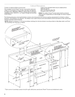
The gas supply line shall be equipped with an approved shutoff valve. This valve should be located in the same area as the Power™ burner and should be in a location that allows ease of opening and closing. Do not block access to the shutoff valve. The valve is for turning on or shutting off gas to the Power™ burner. B A C A. Gas supply line B. Shutoff valve "open" position C. To Power™ burner Natural Gas Conversion Conversion must be made by a qualified gas technician. The qualified Natural gas technician shall provide the Natural gas supply to the selected Power™ burner location in accordance with the National Fuel Gas Code ANSI Z223.1/NFPA 54 - latest edition, and local codes. For conversion to Natural gas, the Natural gas conversion kit supplied with the Power™ burner must be used. IMPORTANT: The gas installation must conform with local codes, or in the absence of local codes, with the National Fuel Gas Code, ANSI Z223.1/NFPA 54 - latest edition. To convert to Natural gas, the Natural Gas Conversion Kit supplied with the Power™ burner must be used. Follow instructions for converting to Natural gas in the "Gas Conversions" section. A B C A. New CSA International approved "outdoor" flexible gas supply line B. Rear of Power™ burner C. To Natural gas supply The gas supply line shall be equipped with an approved shutoff valve. This valve should be located in the same area as the Power™ burner and should be in a location that allows ease of opening and closing. Do not block access to the shutoff valve. The valve is for turning on or shutting off gas to the Power™ burner. B A C A. Gas supply line B. Shutoff valve "open" position C. To Power™ burner INSTALLATION INSTRUCTIONS Built-in Outdoor Power™ Burner Installation WARNING Excessive Weight Hazard Use two or more people to move and install side burner. Failure to do so can result in back or other injury. Install Tank Tray for 20 lb LP Gas Fuel Tank 1. Position the tank tray for 20 lb LP gas fuel tank in the island cabinet. ■ Unpack Power™ burner. Remove all packaging materials and remove Power™ burner from carton. ■ Place Power™ burner into outdoor enclosure, but leave enough room in back to connect to gas supply and electrical single prong plug-in. centerline of tank tray 2¹⁄₄" (5.7 cm) 20⁵⁄₈" (52.4 cm) A 18³⁄₈" (46.7 cm) B A. 8 20.6 cm) B. 16 41.1 cm) 11
-
 1
1 -
2
-
3
-
4
-
5
-
 6
6 -
 7
7 -
 8
8 -
 9
9 -
 10
10 -
 11
11 -
 12
12 -
 13
13 -
 14
14 -
 15
15 -
 16
16 -
17
-
18
-
19
-
20
-
21
-
22
-
23
-
24
-
25
-
26
-
27
-
28
-
29
-
30
-
31
-
32
-
33
-
34
-
35
-
36
-
37
-
38
-
39
-
40
-
41
-
42
-
43
-
44
-
45
-
46
-
47
-
48
 |
 |
