Kyocera KM-C3232E MT-710 Installation Guide - Page 7
EA BC E13 A12
 |
View all Kyocera KM-C3232E manuals
Add to My Manuals
Save this manual to your list of manuals |
Page 7 highlights
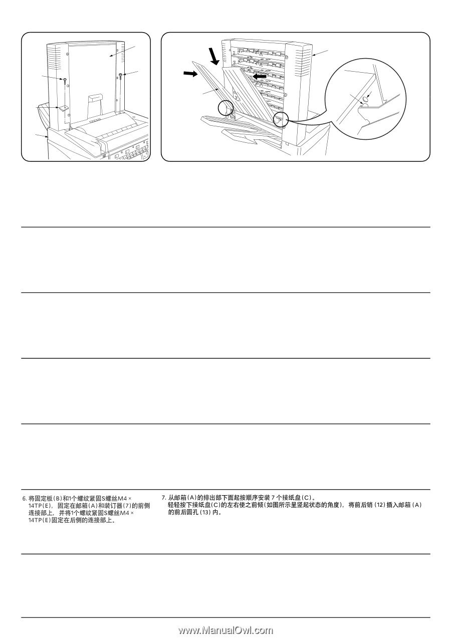
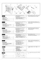
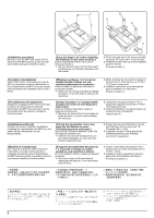
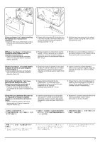
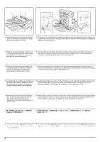
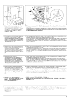
A E E C B 7 A 12 13 6. Secure the front connection portion of the mailbox (A) and the finisher (7) with the mounting plate cover (B) using a TP Taptite S screw M4 × 14 (E) and secure the rear connection portion using a TP Taptite S screw M4 × 14 (E). 7. Fit the seven copy eject bins (C) to the ejection section of the mailbox (A) from the lowest bin to the highest. While pressing both ends of each copy eject bin (C) to bend it a little, fit the bin at a nearly upright angle as shown in the illustration by inserting the front and rear pins (12) into the round holes (13) at the front and rear of the mailbox (A). 6. Fixer la partie de connexion avant de la boîte à lettres (A) et du retoucheur (7) avec le couvercle de plaque de montage (B) à l'aide d'une vis TP Taptite S M4 × 14 (E), et fixer la partie de connexion arrière à l'aide d'une Vis TP Taptite S M4 × 14 (E). 7. Fixer les sept cases d'éjection de copies (C) sur la section d'éjection de la boîte à lettres (A), en procédant de la case située tout en bas à celle située tout en haut. Tout en appuyant sur les deux extrémités de chaque case d'éjection de copies (C) de manière à la plier légèrement, fixer la case à un angle presque droit, comme indiqué sur l'illustration, en insérant les broches avant et arrière (12) dans les trous ronds (13) situés à l'avant et à l'arrière de la boîte à lettres (A). 6. Asegure la parte de conexión delantera del buzón de correo (A) y finalizador (7) con la cubierta de la placa de montaje (B) utilizando un tornillo de TP Taptite S M4 × 14 (E) y asegure la parte de conexión trasera utilizando un tornillo de TP Taptite S M4 × 14 (E). 7. Fije las siete bandejas de expulsión de copias (C) en la sección de expulsión del buzón de correo (A) de la bandeja más baja a la más alta. Mientras presiona ambos extremos de cada bandeja de expulsión de copias (C) para doblarlo un poco, fije la bandeja en un ángulo casi vertical tal como en la figura, insertando los pasadores delantero y trasero (12) en los orificios redondos (13) en los lados delantero y trasero del buzón de correo (A). 6. Befestigen Sie den vorderen Verbindungsabschnitt der Mailbox (A) und des Finishers (7) mit der Abdeckung der Montageplatte (B) und einer TP Taptite SSchraube M4 × 14 (E), und befestigen Sie den hinteren Verbindungsabschnitt mit einer TP Taptite S-Schraube M4 × 14 (E). 7. Setzen Sie die sieben Kopienausgabefächer (C) in den Ausgabeabschnitt der Mailbox (A) ein, beginnend vom untersten Fach zum höchsten. Drücken Sie bei jedem Kopienausgabefach (C) beide Enden zusammen, um es ein wenig zu biegen, und setzen Sie dabei das Fach in einem fast aufrechten Winkel ein, wie in der Abbildung dargestellt, indem Sie den vorderen und hinteren Stift (12) in die Rundlöcher (13) an der Vorderund Rückseite der Mailbox (A) einsetzen. 6. Fissare la parte di collegamento anteriore della casella postale (A) e del finitore (7) con il coperchio della piastra di montaggio (B) utilizzando una vite TP Taptite S M4 × 14 (E) e fissare la parte di collegamento posteriore utilizzando una vite TP Taptite S M4 × 14 (E). 7. Installare i sette scomparti di espulsione delle copie (C) nella parte di espulsione della casella postale (A), cominciando dallo scomparto più in basso fino a quello più in alto. Premendo alle due estremità di uno scomparto di emissione delle copie (C) in modo da piegarle un poco, installare lo scomparto come mostrato in illustrazione mantenendolo quasi ad angolo retto inserendo i perni anteriore e posteriore (12) nei fori rotondi (13) che si trovano sul davanti e sul dietro della parte di fondo della casella postale (A). 6 A 7 B M4 × 14TP S(E)1 M4 × 14TP S(E)1 7 C)7 A C 12 A 13 5
-
 1
1 -
 2
2 -
 3
3 -
 4
4 -
 5
5 -
 6
6 -
 7
7 -
 8
8 -
 9
9 -
 10
10 -
 11
11 -
 12
12
 |
 |