LG DLEC733W Owners Manual - Page 10
lectrical, Requirement, For E - dryer reviews
 |
View all LG DLEC733W manuals
Add to My Manuals
Save this manual to your list of manuals |
Page 10 highlights
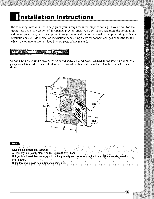
lectrical Requirement For E Review the following options to determine the appropriate electrical connection for your home: Use the instructions hi this section :if your home has a 4-wire receptacle (NEMA type 14-30R) and you will be using a UL listed, 120/240 volt minimum,. 30 amp, dryer power supply cord. Ise the instructions in this section if your home has a 3-wire receptacle (NEMA type 10=30R) and you will t_e using a IL listed., 120/240 volt n_ininmm, 3(i) amp, dryer power supply cord. If this type is available at your home. you will k,e connecting to a :tused discolmect or circuit breaker box It' this type is available at your home. you will connecting to a Oa_d disconnect or circuit breaker t_x • Screw powersupplywire to the terminalbl_ Coloredwire shouldhe conn_ed to samecolor screw.Wire colorindicatedonmanualis connectedto thesame colorscrew in block. Othe_ise, excessivecurrentis appliedresulting in damageson productand heatingfailure. • [)irect-wi re connections _ not meet the building coderegulationsin most areas. It is the customer'sresponsibility to ensurethat the installationmeets all suchrequirements. Important : Grounding through the neutral conductor is p¢ohiNted tor(l) new brm_ch-circuit installations, (2) mobile homes, and (3) recreational vehicles, and (4) areas where local codes prohibit grounding through the neutral conductor. Prepare minimum 5ft (1.52m) of length in order for dryer to _ :replaced. First, peel 5 inches (12.7cm) of covering material from end. Strip 5 inches of ground wire insulation. After cutting 1"/2inch (3.8cm) t_3m 3 other wi_s peel insulation back linch (2.5cm). Make ends of 3 wires a hook sha_. ,¢ Then, put the h_ked shape end of the wire under the screw of the mnninal bl_k (h_ked end facing rightward) and pinch the hook together and screw tightly. 1. Connect neutral wi_ (white) of power cord to center terminal block screw. 2. Connect red and black wire to the left and right terminal bl_k screws. 3. Connect ground wire }green) of power cord to external ground screx_ and the move neutral ground ,_,:ireof a}pliance and connect it to center scow. 4. Make sure that the strain relief screw is tightened. and be sure that N1 terminN block imts are on tight and power cord is in right position. C_r terminal Nook scr_ Neutral grounding NeL_r_l wire (white Orcenter _) Green wire of _ _d _re_
-
 1
1 -
2
-
3
-
4
-
 5
5 -
 6
6 -
 7
7 -
 8
8 -
 9
9 -
 10
10 -
 11
11 -
 12
12 -
 13
13 -
 14
14 -
 15
15 -
16
-
17
-
18
-
19
-
20
-
21
-
22
-
23
-
24
-
25
-
26
-
27
-
28
-
29
-
30
-
31
-
32
-
33
-
34
-
35
-
36
-
37
-
38
-
39
-
40
-
41
-
42
-
43
-
44
-
45
-
46
-
47
-
48
-
49
-
50
-
51
-
52
-
53
-
54
-
55
-
56
-
57
-
58
-
59
-
60
-
61
-
62
-
63
-
64
 |
 |
