LG HBLG2350E Service Manual - Page 8
Power Cord, 3.5 Thermistor, 3.6 Synchronous Motor - appliances
 |
View all LG HBLG2350E manuals
Add to My Manuals
Save this manual to your list of manuals |
Page 8 highlights
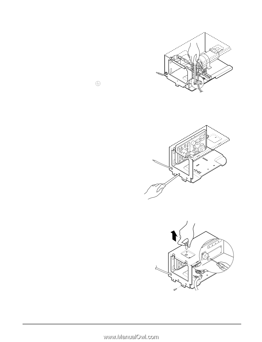
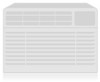
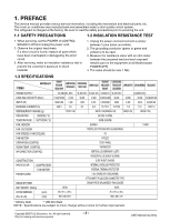
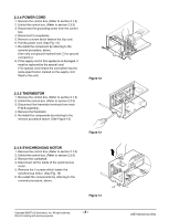
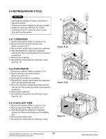
2.3.4 POWER CORD 1. Remove the control box. (Refer to section 2.1.3) 2. Unfold the control box. (Refer to section 2.3.3) 3. Disconnect the grounding screw from the control box. 4. Disconnect 2 receptacles. 5. Remove a screw which fastens the clip cord. 6. Pull the power cord. (See Fig. 12) 7. Re-install the component by referring to the removal procedure, above. (Use only one ground-marked hole for ground connection.) 8. If the supply cord of this appliance is damaged, it must be replaced by the special cord. (The special cord means the cord which has the same specification marked on the supply cord fitted to the unit.) Figure 12 2.3.5 THERMISTOR 1. Remove the control box. (Refer to section 2.1.3) 2. Unfold the control box. (Refer to section 2.3.3) 3. Disconnect the thermistor terminals from main P.W.B assembly. 4. Remove the thermistor. 5. Re-install the components by referring to the removal procedure above. (See Figure 13) Figure 13 2.3.6 SYNCHRONOUS MOTOR 1. Remove the control box. (Refer to section 2.1.3) 2. Unfold the control box. (Refer to section 2.3.3) 3. Remove the crankshaft. 4. Disconnect all the leads of the synchronous motor. 5. Remove the 2 screws which fasten the synchronous motor. (See Fig. 14) 6. Re-install the components by referring to the removal procedure, above. Figure 14 Copyright ©2007 LG Electronics. Inc. All right reserved. Only for training and service purposes -8- LGE Internal Use Only
-
 1
1 -
2
-
 3
3 -
 4
4 -
 5
5 -
 6
6 -
 7
7 -
 8
8 -
 9
9 -
 10
10 -
 11
11 -
 12
12 -
 13
13 -
14
-
15
-
16
-
17
-
18
-
19
-
20
-
21
-
22
-
23
-
24
-
25
-
26
-
27
-
28
-
29
-
30
-
31
 |
 |