LG HBLG2350E Service Manual - Page 9
Refrigeration Cycle
 |
View all LG HBLG2350E manuals
Add to My Manuals
Save this manual to your list of manuals |
Page 9 highlights
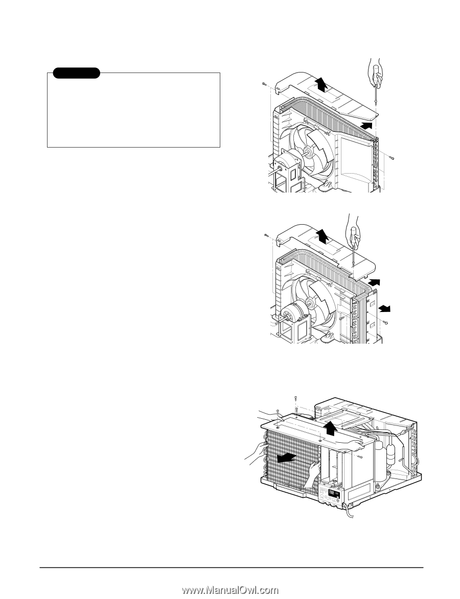
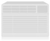
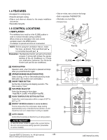
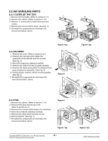
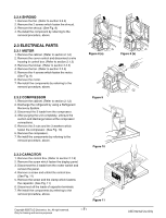
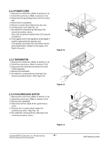
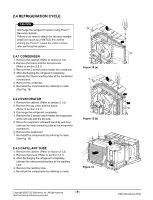
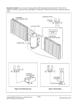
2.4 REFRIGERATION CYCLE CAUTION Discharge the refrigerant system using FreonTM Recovery System. If there is no valve to attach the recovery system, install one (such as a WATCO A-1) before venting the FreonTM. Leave the valve in place after servicing the system. 2.4.1 CONDENSER 1. Remove the cabinet. (Refer to section 2.1.2) 2. Remove the brace and the shroud cover. (Refer to section 2.2.1) 3. Remove the 5 screws which fasten the condenser. 4. After discharging the refrigerant completely, unbraze the interconnecting tube at the condenser connections. 5. Remove the condenser. 6. Re-install the components by referring to notes. (See Fig. 15) 2.4.2 EVAPORATOR 1. Remove the cabinet. (Refer to section 2.1.2) 2. Remove the top cover and the brace. (Refer to section 2.2.1) 3. Discharge the refrigerant completely. 4. Remove the 3 screws which fasten the evaporator at the left side and the top side. 5. Move the evaporator sideward carefully and then unbraze the interconnecting tube at the evaporator connectors. 6. Remove the evaporator. 7. Re-install the components by referring to notes. (See Fig. 16) 2.4.3 CAPILLARY TUBE 1. Remove the cabinet. (Refer to section 2.1.2) 2. Remove the brace. (Refer to section 2.2.1) 3. After discharging the refrigerant completely, unbraze the interconnecting tube at the capillary tube. 4. Remove the capillary tube. 5. Re-install the components by referring to notes. Figure 15 (a) Figure 15 (b) Figure 16 Copyright ©2007 LG Electronics. Inc. All right reserved. Only for training and service purposes -9- LGE Internal Use Only
-
 1
1 -
2
-
3
-
 4
4 -
 5
5 -
 6
6 -
 7
7 -
 8
8 -
 9
9 -
 10
10 -
 11
11 -
 12
12 -
 13
13 -
 14
14 -
15
-
16
-
17
-
18
-
19
-
20
-
21
-
22
-
23
-
24
-
25
-
26
-
27
-
28
-
29
-
30
-
31
 |
 |