LG L1404R Owners Manual - Page 19
Fig. 5, Fig. 6, Fig. 7, Fig. 8
 |
View all LG L1404R manuals
Add to My Manuals
Save this manual to your list of manuals |
Page 19 highlights
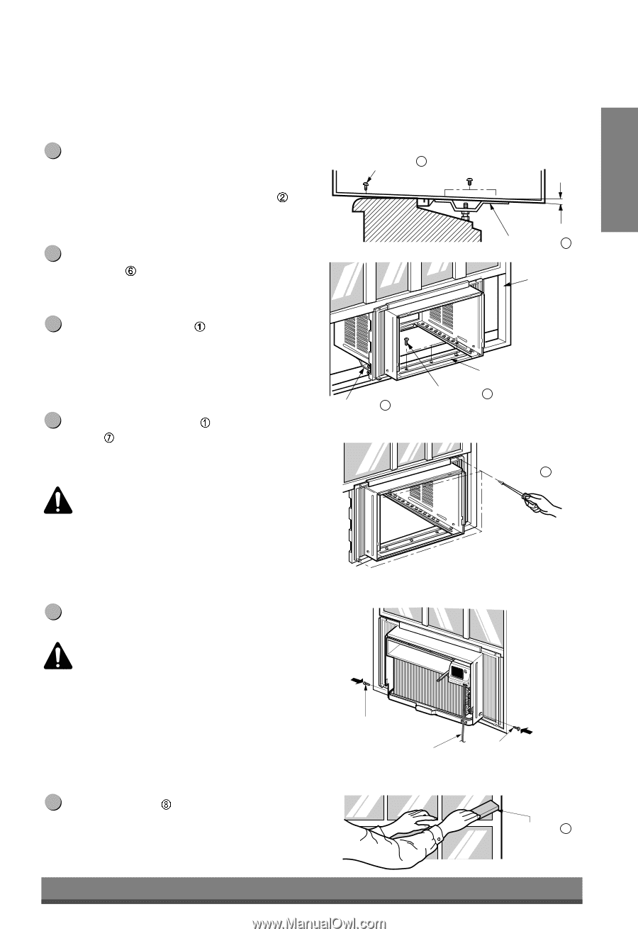
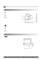
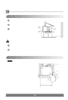
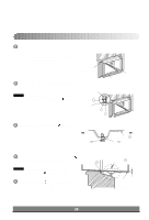
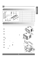
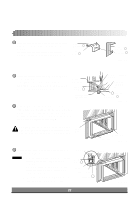
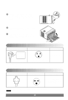
ENGLISH About 1/2" 6 The cabinet should be installed with a very slight tilt (about 1/2") downward toward the outside (See Fig. 5). Adjust the bolt and the nut of Sill Support for balancing the cabinet. Screw(Type B) 6 7 Attach the cabinet to the window stool by driving the screws (Type B: Length 16mm (5/8 inch) and below.) through the front angle into window stool. 8 Pull each Frame Curtain fully to each window sash track, and repeat step 2. Sill Support 2 Sash track Sill Support 2 9 Attach each Frame Curtain the window sash using screws (Type C). (See Fig. 6) Front Angle Screw(Type B) 6 Fig. 5 CAUTION: Do not drill a hole in the bottom pan. The unit is designed to operate with approximately 1/2" of water in bottom pan. There is no need to add water if the pan is dry. Type C 7 Fig. 6 10 Slide the unit into the cabinet. (See Fig. 7) CAUTION: For security purpose, reinstall screws (Type A) at cabinet's sides. Screw(Type A) Power cord Screw (Type A) Fig. 7 11 Cut the Foam-Strip to the proper length and insert between the upper window sash and the lower window sash. (See Fig. 8) 19 Foam-Strip 8 Fig. 8
-
 1
1 -
2
-
3
-
4
-
5
-
6
-
7
-
8
-
9
-
10
-
11
-
12
-
13
-
 14
14 -
 15
15 -
 16
16 -
 17
17 -
 18
18 -
 19
19 -
 20
20 -
 21
21 -
 22
22 -
 23
23 -
 24
24 -
25
-
26
-
27
-
28
 |
 |