LG MA8000ST Service Manual - Page 15
Gross, Assembly, Removal, Voltage, Transformer, Motor, Capacitor, Diode
 |
View all LG MA8000ST manuals
Add to My Manuals
Save this manual to your list of manuals |
Page 15 highlights
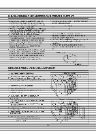
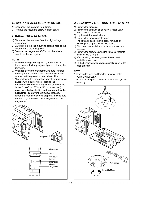
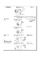
D. DOOR GROSS ASSEMBLY REMOVAL (1) Open the door. (2) Life up and draw the door CAUTION : Be careful not to damage door seal plate with the screwdriver. NOTE: 1. After replacing the door, be sure to check that the primary switch, monitor switch, and secondary switch operate normally. 2. After replacing the door, check for microwave energy leakage with a survey meter. Microwave energy must be below the limit of 5 mW/cm2. (with a 275 ml water load) 3. When mounting the door assembly to the oven assembly, be sure to adjust the door assembly parallel to the chassis. Also adjust so the door has no play between the inner door surface and oven frame assembly. If the door assembly is not mounted properly, microwaves may leak from the clearance between the door and the oven. Remove door assembly E. HIGH VOLTAGE TRANSFORMER REMOVAL 1) Discharge the high voltage capacitor. 2) Disconnect the leadwire from magnetron, high voltage transformer, and capacitor. 3) Remove the screw holding the high voltage transformer to the baseplate. F. FAN MOTOR ASSEMBLY REMOVAL 1) Discharge the high voltage capacitor. 2) Disconnect the leadwire from fan motor, and high voltage capacitor. 3) Remove the two screws holding the the suction guide ASS'Y to the oven cavity and remove the high voltage diode earth screw. 4) Remove the two screws holding the fan motor ASS'Y to the suction guide ASS'Y. G. HIGH VOLTAGE CAPACITOR AND DIODE REMOVAL 1) Discharge the high voltage capacitor. 2) Disconnect the leadwire from fan motor, and high voltage capacitor. 3) Remove the screw holding the suction guide ASS'Y to the oven cavity and remove the high voltage diode earth screw. 4) Remove the screw holding the high voltage capacitor bracket. Fan Motor ASS'Y IqpA ••'44 ,o• • P5' Suction -"1, Guide H.V. Capacitor H.V. Transformer H.V. Diode say • 5-4
-
 1
1 -
2
-
3
-
4
-
5
-
6
-
7
-
8
-
9
-
 10
10 -
 11
11 -
 12
12 -
 13
13 -
 14
14 -
 15
15 -
 16
16 -
 17
17 -
 18
18 -
 19
19 -
 20
20 -
21
-
22
-
23
-
24
-
25
-
26
-
27
-
28
-
29
-
30
-
31
-
32
-
33
-
34
-
35
 |
 |
