LG MA8000ST Service Manual - Page 18
Components
 |
View all LG MA8000ST manuals
Add to My Manuals
Save this manual to your list of manuals |
Page 18 highlights
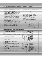
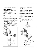
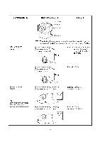
WARNING • FOR CONTINUED PROTECTION AGAINST EXCESSIVE RADIATION EMISSION, REPLACE ONLY WITH IDENTICAL REPLACEMENT PARTS TYPE NO. SZM-V 1G-FA-63 OR VP-533A-Or FOR PRIMARY SWITCH TYPF NO S7M V 16 FA 62 OR VP 532A OF FOR MONITOR SWITCH TYPE NO. SZM-V 16-FA-63 OR VP-533A-OF FOR SECONDARY SWITCH When the door release button is depressed slowly with the door c osed, an audible click should be heard at the same time or successively at Disconnect the wire lead from the seconda' switch Connect the ohmmeter leads to the common latches should activate the switches with an audib e click If the atchcs do not activate the switches when switch The meter should indicate a open circuit in the door open condition When the door is closed, meter should indicate an closed circuit. When the adjusted in accordance with the adjustment procedure. Disconnect the wire lead from the primary switc Connect the oimmeter eads to the common (COM) and normally open (NO) terminal of the switch The meter should indicate an open circuit in the door open condition. When the door is closed, tie meter should indicate a closed circuit When the primary switch operation is abnormal, make the necessary adjustment or replace the switch only with the same type of switch necessary adjustment or replace the switch only with the same type of switch. C. MONITOR SWITCH TEST Disconnect the wire lead from the monitor switch. Connect the ohmmeter leads to the common (COM) and normally closed (NC) terminals of the switch. The meter should indicate closed circuit in the door open condition. When the door is closed, meter should indicate an open circuit. When the monitor switch operation is aonormal, replace with the same type of switch. NOTE. After repairing the door or the interlock test before operating the oven COMPONENTS SWITCHES (Wire leads removed) TEST PROCEDURE Check for continuity of the switch with an Ohm meter RESULTS Door open Door closed 0 Primary NO OD Switch Monitor Switch 0 NC COM (-1 0 Secondary rTh NO CO Switch COM NOTE • After chec King for the continuity of switches, make sure that they are connected correctly. 5-7
-
 1
1 -
2
-
3
-
4
-
5
-
6
-
7
-
8
-
9
-
10
-
11
-
12
-
 13
13 -
 14
14 -
 15
15 -
 16
16 -
 17
17 -
 18
18 -
 19
19 -
 20
20 -
 21
21 -
 22
22 -
 23
23 -
24
-
25
-
26
-
27
-
28
-
29
-
30
-
31
-
32
-
33
-
34
-
35
 |
 |
