LG MA8000ST Service Manual - Page 17
Assembly, Removal, Interlock, System
 |
View all LG MA8000ST manuals
Add to My Manuals
Save this manual to your list of manuals |
Page 17 highlights
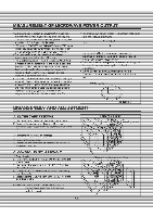
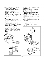
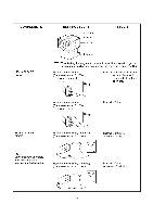
K. PCB ASSEMBLY REMOVAL liftemoysalhaconlioLpanef assembly from Lhe cavity. panel assembly removal on previous page.) 2) Remove screws which hold the I5C1I-SUWASSR1c the control-per .el. 3) Disconnect the flat cable from the PCB SUB ASS'Y and take off the PCB SUB ASS'Y_ ontrot Pa le Key Membrane '-'Cu Sup Asm L. INTERLOCK SYSTEM 1) IN I ERLOCK MECHANISM The door lock-mechanism is a device which has been specially designed-te-elkninate completely microwave activity when the door is opened during cooking and-thus-to-preventthe danger resulting from the-mieroweve-leakage 2) UNTINaoFTRFPRINFARY7MONITOP7 SECONDAHY Swi I CITES 10 I HE LA I CH ARD ADJUSTMENT DIRECTION PRIMARY T MONITO WITCH SECONDARY SWITCH LATCH BOARD TO THE OVFN ASSEMBLY • Mount the latch rd to the overisueembly. • Adjust the latch boa-rd-in the-arrow direction so that oven door will not hame.aa4Lplay-in-it when the door is closed. lighten the mounting screw. • Check for play in the-door-by-pushing-the-etoorrefeaseilidlon. Door movement-should-be-lass than 0.5 mm. (1164 inch) Don't push the door adjustment,.-MMaake sure that the latch moves smo©thly adjustment are completed and that the-screws are tight. Make sure the primary, monitor, and secondary switches operate properly by following-the-continuity test procedure. 5-6
-
 1
1 -
2
-
3
-
4
-
5
-
6
-
7
-
8
-
9
-
10
-
11
-
 12
12 -
 13
13 -
 14
14 -
 15
15 -
 16
16 -
 17
17 -
 18
18 -
 19
19 -
 20
20 -
 21
21 -
 22
22 -
23
-
24
-
25
-
26
-
27
-
28
-
29
-
30
-
31
-
32
-
33
-
34
-
35
 |
 |
