Lenovo B50-45 Hardware Maintenance Manual - Lenovo B50-xx, B50-30 Touch Notebo - Page 46
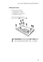
Removal, steps, keyboard, continued, disconnect, connector, direction, shown, arrows, careful
 |
View all Lenovo B50-45 manuals
Add to My Manuals
Save this manual to your list of manuals |
Page 46 highlights
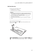
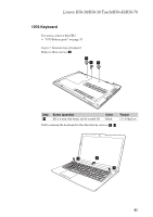
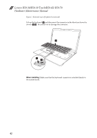
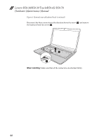
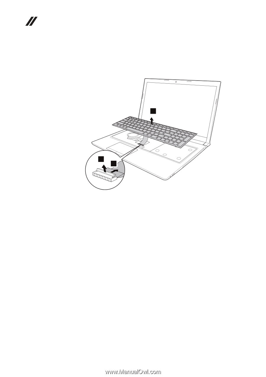
Lenovo B50-30/B50-30 Touch/B50-45/ B50-70 Hardware Maintenance Manual Figure 7. Removal steps of keyboard (continued) Lift up the keyboard d and disconnect the connector in the direction shown by arrows e f. Be careful not to damage the connector. . 4 5 6 When installing: Make sure that the keyboard connector is attached firmly to the system board. 42
-
 1
1 -
2
-
3
-
4
-
5
-
6
-
7
-
8
-
9
-
10
-
11
-
12
-
13
-
14
-
15
-
16
-
17
-
18
-
19
-
20
-
21
-
22
-
23
-
24
-
25
-
26
-
27
-
28
-
29
-
30
-
31
-
32
-
33
-
34
-
35
-
36
-
37
-
38
-
39
-
40
-
 41
41 -
 42
42 -
 43
43 -
 44
44 -
 45
45 -
 46
46 -
 47
47 -
 48
48 -
 49
49 -
 50
50 -
 51
51 -
52
-
53
-
54
-
55
-
56
-
57
-
58
-
59
-
60
-
61
-
62
-
63
-
64
-
65
-
66
-
67
-
68
-
69
-
70
-
71
-
72
-
73
-
74
-
75
-
76
-
77
-
78
-
79
-
80
-
81
-
82
-
83
-
84
-
85
-
86
-
87
-
88
 |
 |
Lenovo B50-30/B50-30 Touch/B50-45/ B50-70
Hardware Maintenance Manual
42
Figure
7.
Removal
steps
of
keyboard
(continued)
Lift
up
the
keyboard
and
disconnect
the
connector
in
the
direction
shown
by
arrows
Be
careful
not
to
damage
the
connector.
.
When installing:
Make
sure
that
the
keyboard
connector
is
attached
firmly
to
the
system
board.
d
e
f
4
5
6