Lenovo B50-45 Hardware Maintenance Manual - Lenovo B50-xx, B50-30 Touch Notebo - Page 67
Antenna, LCD cable, and integrated camera, Disconnect
 |
View all Lenovo B50-45 manuals
Add to My Manuals
Save this manual to your list of manuals |
Page 67 highlights
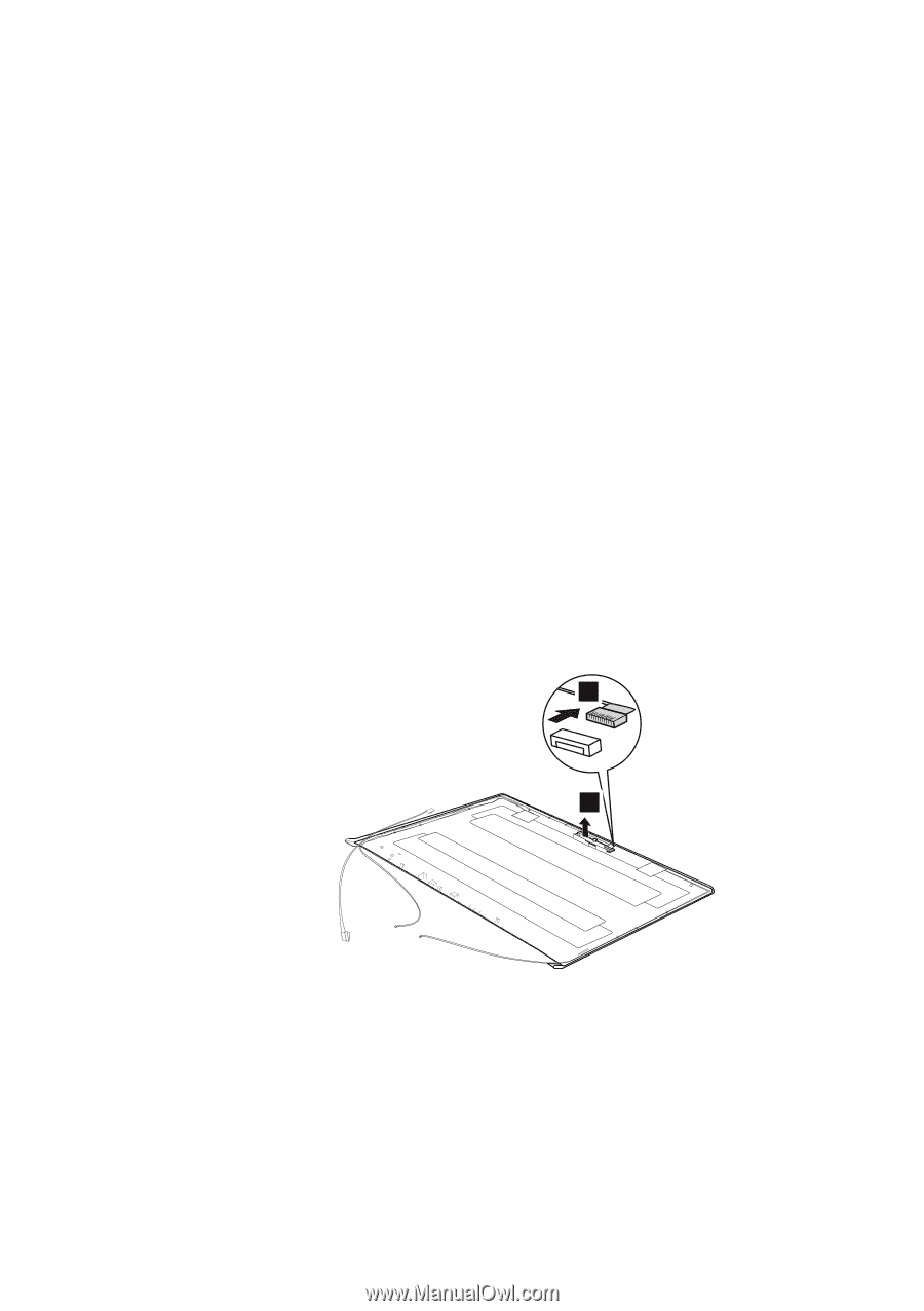
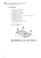
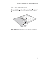
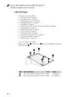
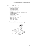
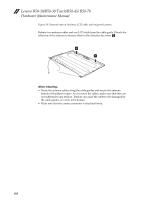
Lenovo B50-30/B50-30 Touch/B50-45/B50-70 1200 Antenna, LCD cable, and integrated camera For access, remove these FRUs in order: • "1010 Battery pack" on page 33 • "1020 Optical drive" on page 34 • "1030 Bottom slot cover" on page 36 • "1040 Hard disk drive" on page 37 • "1050 DIMM" on page 39 • "1060 PCI Express Mini Card for wireless LAN/WAN" on page 40 • "1070 Keyboard" on page 41 • "1080 Keyboard bezel" on page 43 • "1110 Led board" on page 48 • "1130 System board" on page 50 • "1160 LCD unit and base cover" on page 55 • "1170 LCD front bezel" on page 59 • "1180 LCD panel" on page 60 • "1190 LCD hinges" on page 62 Figure 20. Removal steps of Antenna, LCD cable, and integrated camera Disconnect the camera connector in the direction shown by arrow a. Remove the camera from the LCD cover in the direction by arrow b. 1 2 2 63
-
 1
1 -
2
-
3
-
4
-
5
-
6
-
7
-
8
-
9
-
10
-
11
-
12
-
13
-
14
-
15
-
16
-
17
-
18
-
19
-
20
-
21
-
22
-
23
-
24
-
25
-
26
-
27
-
28
-
29
-
30
-
31
-
32
-
33
-
34
-
35
-
36
-
37
-
38
-
39
-
40
-
41
-
42
-
43
-
44
-
45
-
46
-
47
-
48
-
49
-
50
-
51
-
52
-
53
-
54
-
55
-
56
-
57
-
58
-
59
-
60
-
61
-
 62
62 -
 63
63 -
 64
64 -
 65
65 -
 66
66 -
 67
67 -
 68
68 -
 69
69 -
 70
70 -
 71
71 -
 72
72 -
73
-
74
-
75
-
76
-
77
-
78
-
79
-
80
-
81
-
82
-
83
-
84
-
85
-
86
-
87
-
88
 |
 |