Lenovo B50-45 Hardware Maintenance Manual - Lenovo B50-xx, B50-30 Touch Notebo - Page 55
Removal, steps, system, board, continued, Disconnect, connector, direction, shown, arrow
 |
View all Lenovo B50-45 manuals
Add to My Manuals
Save this manual to your list of manuals |
Page 55 highlights
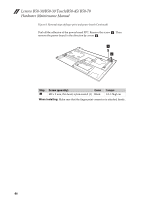
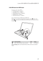
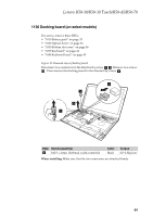
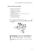
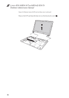
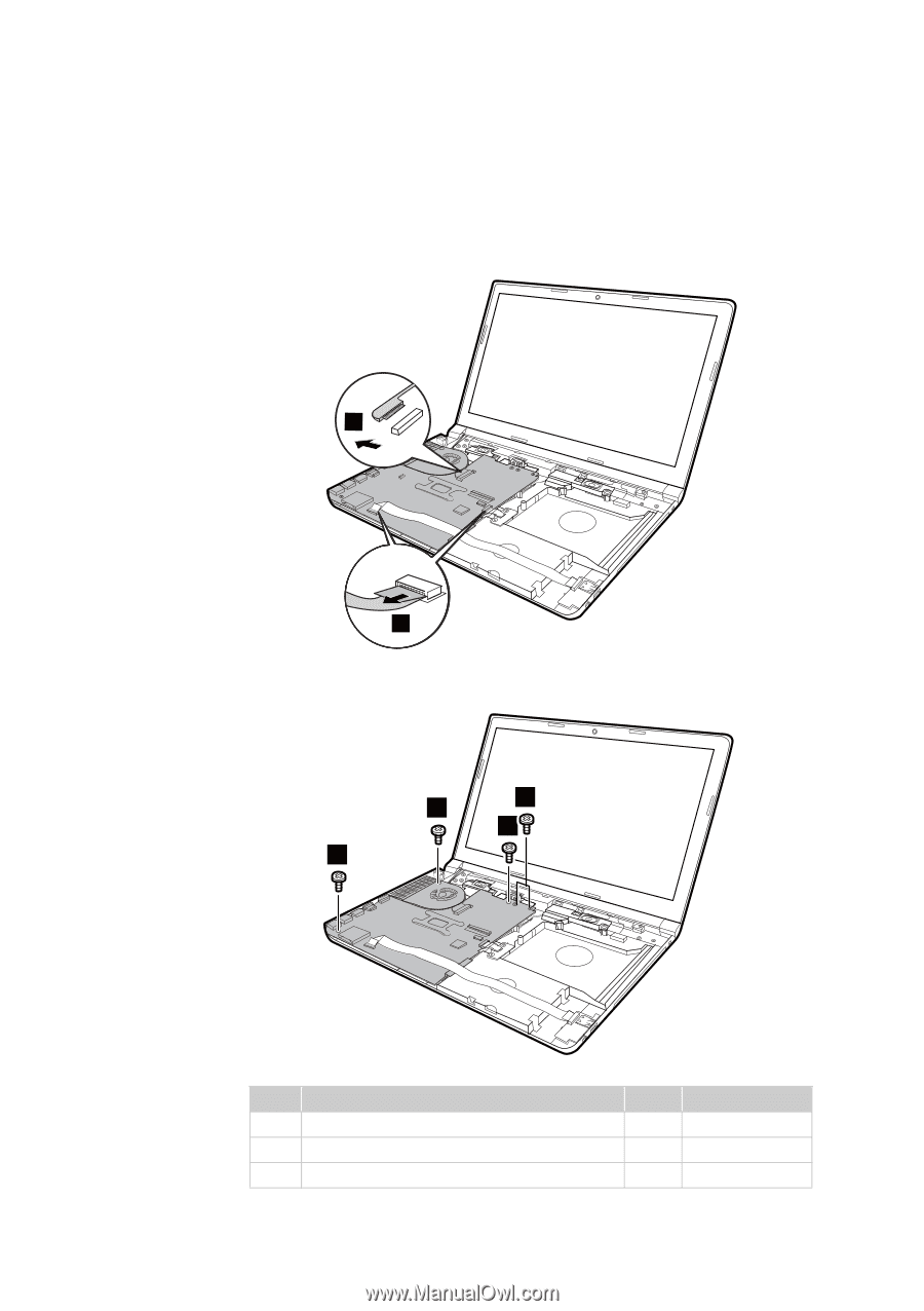
Lenovo B50-30/B50-30 Touch/B50-45/B50-70 Figure 13. Removal steps of system board (continued) Disconnect the ODD board connector and the USB board connector in the direction shown by arrow b . Then disconnect the EDP connector in the direction shown by arrow c . 3 2 Remove two screws d , screw e and two screws f . 6 5 4 4 Step 7 d 7 d e 7 d f Screw (quantity) M2.5 x 4 mm, flat‐head, nylok‐coated (2) M2 x 5 mm, flat‐head, nylok‐coated (1) M2 x 3 mm, flat‐head, nylok‐coated (2) Color Torque Black 2.0~2.5kgf.cm Silver 1.5~2.0kgf.cm Black 1.0~1.5kgf.cm 51
-
 1
1 -
2
-
3
-
4
-
5
-
6
-
7
-
8
-
9
-
10
-
11
-
12
-
13
-
14
-
15
-
16
-
17
-
18
-
19
-
20
-
21
-
22
-
23
-
24
-
25
-
26
-
27
-
28
-
29
-
30
-
31
-
32
-
33
-
34
-
35
-
36
-
37
-
38
-
39
-
40
-
41
-
42
-
43
-
44
-
45
-
46
-
47
-
48
-
49
-
 50
50 -
 51
51 -
 52
52 -
 53
53 -
 54
54 -
 55
55 -
 56
56 -
 57
57 -
 58
58 -
 59
59 -
 60
60 -
61
-
62
-
63
-
64
-
65
-
66
-
67
-
68
-
69
-
70
-
71
-
72
-
73
-
74
-
75
-
76
-
77
-
78
-
79
-
80
-
81
-
82
-
83
-
84
-
85
-
86
-
87
-
88
 |
 |
Lenovo B50-30/B50-30 Touch/B50-45/B50-70
51
Figure
13.
Removal
steps
of
system
board
(continued)
Disconnect
the
ODD
board
connector
and
the
USB
board
connector
in
the
direction
shown
by
arrow
.
Then
disconnect
the
EDP
connector
in
the
direction
shown
by
arrow
.
Remove
two
screws
,
screw
and
two
screws
.
Step
Screw (quantity)
Color
Torque
M2.5
x
4
mm,
flat
‐
head,
nylok
‐
coated
(2)
Black
2.0~2.5kgf.cm
M2
x
5
mm,
flat
‐
head,
nylok
‐
coated
(1)
Silver
1.5~2.0kgf.cm
M2
x
3
mm,
flat
‐
head,
nylok
‐
coated
(2)
Black
1.0~1.5kgf.cm
b
c
2
3
d
e
f
5
4
4
6
d
e
f