Lenovo IdeaPad S10-3c Lenovo IdeaPad S10-3c Hardware Maintenance Manual - Page 59
Fan assembly and Heat Sink assembly
 |
View all Lenovo IdeaPad S10-3c manuals
Add to My Manuals
Save this manual to your list of manuals |
Page 59 highlights
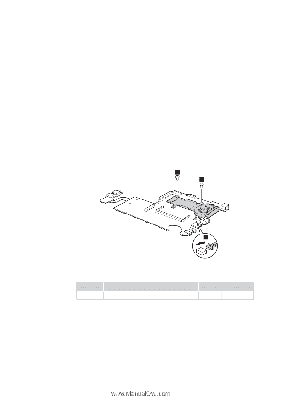
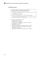
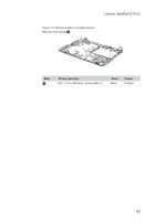
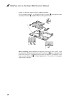
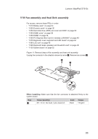
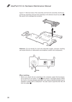
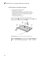
Lenovo IdeaPad S10-3c 1110 Fan assembly and Heat Sink assembly For access, remove these FRUs in order: •• "1010 Battery pack" on page 34 •• "1020 Dummy cards" on page 35 •• "1030 Hard disk drive (HDD) slot cover and HDD" on page 36 •• "1040 DIMM cover" on page 38 •• "1050 DIMM" on page 39 •• "1060 PCI Express Mini Card for wireless LAN/WAN" on page 40 •• "1070 Keyboard cover, keyboard and LED board" on page 42 •• "1080 LCD unit" on page 45 •• "1090 Keyboard bezel, speakers and bluetooth card" on page 48 •• "1100 System board" on page 52 Figure 11. Removal steps of fan assembly and heat sink assembly Unplug the connector in the direction shown by arrow 1. Remove two screws 2. 2 2 1 When installing: Make sure that the fan connector is attached firmly to the system board. Step 2 Screw (quantity) M2 × 3 mm, flat-head, nylok-coated (2) Color Black Torque 1.5 kgfcm 55
-
 1
1 -
2
-
3
-
4
-
5
-
6
-
7
-
8
-
9
-
10
-
11
-
12
-
13
-
14
-
15
-
16
-
17
-
18
-
19
-
20
-
21
-
22
-
23
-
24
-
25
-
26
-
27
-
28
-
29
-
30
-
31
-
32
-
33
-
34
-
35
-
36
-
37
-
38
-
39
-
40
-
41
-
42
-
43
-
44
-
45
-
46
-
47
-
48
-
49
-
50
-
51
-
52
-
53
-
 54
54 -
 55
55 -
 56
56 -
 57
57 -
 58
58 -
 59
59 -
 60
60 -
 61
61 -
 62
62 -
 63
63 -
 64
64 -
65
-
66
-
67
-
68
-
69
-
70
-
71
-
72
-
73
-
74
-
75
-
76
-
77
-
78
-
79
-
80
-
81
-
82
-
83
-
84
-
85
-
86
-
87
-
88
 |
 |