Lenovo IdeaPad S10-3c Lenovo IdeaPad S10-3c Hardware Maintenance Manual - Page 68
Antenna assembly and LCD cover
 |
View all Lenovo IdeaPad S10-3c manuals
Add to My Manuals
Save this manual to your list of manuals |
Page 68 highlights
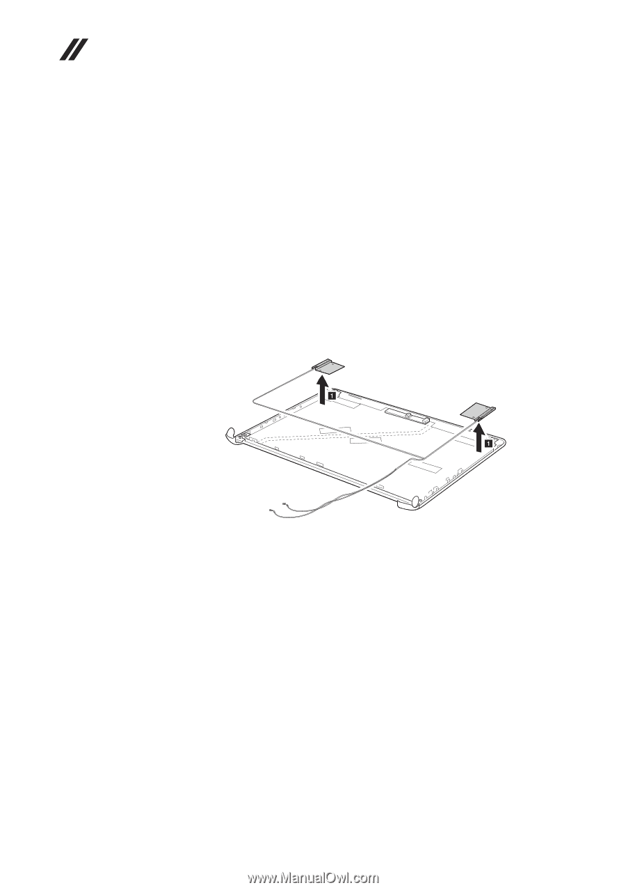
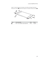
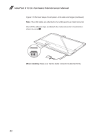
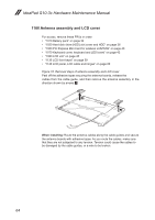
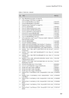
IdeaPad S10-3c Hardware Maintenance Manual 1160 Antenna assembly and LCD cover For access, remove these FRUs in order: •• "1010 Battery pack" on page 34 •• "1030 Hard disk drive (HDD) slot cover and HDD" on page 36 •• "1060 PCI Express Mini Card for wireless LAN/WAN" on page 40 •• "1070 Keyboard cover, keyboard and LED board" on page 42 •• "1080 LCD unit" on page 45 •• "1130 LCD front bezel" on page 59 •• "1140 LCD panel, LCD cable and hinges" on page 60 Figure 16. Removal steps of antenna assembly and LCD cover Peel off the adhesive tapes securing the antenna boards, release the cables from the cable guide, and then remove the antenna assembly in the direction shown by arrows 1. When installing: Route the antenna cables along the cable guides and secure the antenna boards with adhesive tapes. As you route the cables, make sure that they are not subjected to any tension. Tension could cause the cables to be damaged by the cable guides, or a wire to be broken. 64
-
 1
1 -
2
-
3
-
4
-
5
-
6
-
7
-
8
-
9
-
10
-
11
-
12
-
13
-
14
-
15
-
16
-
17
-
18
-
19
-
20
-
21
-
22
-
23
-
24
-
25
-
26
-
27
-
28
-
29
-
30
-
31
-
32
-
33
-
34
-
35
-
36
-
37
-
38
-
39
-
40
-
41
-
42
-
43
-
44
-
45
-
46
-
47
-
48
-
49
-
50
-
51
-
52
-
53
-
54
-
55
-
56
-
57
-
58
-
59
-
60
-
61
-
62
-
 63
63 -
 64
64 -
 65
65 -
 66
66 -
 67
67 -
 68
68 -
 69
69 -
 70
70 -
 71
71 -
 72
72 -
 73
73 -
74
-
75
-
76
-
77
-
78
-
79
-
80
-
81
-
82
-
83
-
84
-
85
-
86
-
87
-
88
 |
 |