Lenovo J115 Hardware Maintenance Manual - Page 104
Replacing a memory module, Remove the cover. See Removing the cover
 |
View all Lenovo J115 manuals
Add to My Manuals
Save this manual to your list of manuals |
Page 104 highlights
3. Remove the two screws at the front of the chassis securing the drive bay assembly. 4. Slide the drive bay assembly forward until it stops. Disconnect the power supply and signal cables from the drives. Pivot the rear of the drive bay assembly upward to remove it completely from the computer. Note: To allow easier access to the cables, lift the fan plenum off the heat sink. See "Locations" on page 94. 5. Reverse this procedure to replace the drive bay assembly and bezel. Replacing a memory module 1. Remove the cover. See "Removing the cover" on page 94. 98 Hardware Maintenance Manual Lenovo 3000 J Series
-
 1
1 -
2
-
3
-
4
-
5
-
6
-
7
-
8
-
9
-
10
-
11
-
12
-
13
-
14
-
15
-
16
-
17
-
18
-
19
-
20
-
21
-
22
-
23
-
24
-
25
-
26
-
27
-
28
-
29
-
30
-
31
-
32
-
33
-
34
-
35
-
36
-
37
-
38
-
39
-
40
-
41
-
42
-
43
-
44
-
45
-
46
-
47
-
48
-
49
-
50
-
51
-
52
-
53
-
54
-
55
-
56
-
57
-
58
-
59
-
60
-
61
-
62
-
63
-
64
-
65
-
66
-
67
-
68
-
69
-
70
-
71
-
72
-
73
-
74
-
75
-
76
-
77
-
78
-
79
-
80
-
81
-
82
-
83
-
84
-
85
-
86
-
87
-
88
-
89
-
90
-
91
-
92
-
93
-
94
-
95
-
96
-
97
-
98
-
 99
99 -
 100
100 -
 101
101 -
 102
102 -
 103
103 -
 104
104 -
 105
105 -
 106
106 -
 107
107 -
 108
108 -
 109
109 -
110
-
111
-
112
-
113
-
114
-
115
-
116
-
117
-
118
-
119
-
120
-
121
-
122
-
123
-
124
-
125
-
126
-
127
-
128
-
129
-
130
-
131
-
132
-
133
-
134
-
135
-
136
-
137
-
138
-
139
-
140
-
141
-
142
-
143
-
144
-
145
-
146
-
147
-
148
-
149
-
150
-
151
-
152
-
153
-
154
-
155
-
156
-
157
-
158
-
159
-
160
-
161
-
162
-
163
-
164
-
165
-
166
-
167
-
168
-
169
-
170
-
171
-
172
-
173
-
174
-
175
-
176
-
177
-
178
-
179
-
180
-
181
-
182
-
183
-
184
-
185
-
186
-
187
-
188
-
189
-
190
-
191
-
192
-
193
-
194
-
195
-
196
-
197
-
198
-
199
-
200
 |
 |

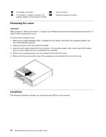
3.
Remove the two screws at the front of the chassis securing the drive bay assembly.
4.
Slide the drive bay assembly forward until it stops. Disconnect the power supply and signal cables from
the drives. Pivot the rear of the drive bay assembly upward to remove it completely from the computer.
Note:
To allow easier access to the cables, lift the fan plenum off the heat sink. See “Locations”
on page 94.
5.
Reverse this procedure to replace the drive bay assembly and bezel.
Replacing a memory module
1.
Remove the cover. See “Removing the cover” on page 94.
98
Hardware Maintenance Manual Lenovo 3000 J Series