Lenovo J115 Hardware Maintenance Manual - Page 85
Notes, Important, the socket.
 |
View all Lenovo J115 manuals
Add to My Manuals
Save this manual to your list of manuals |
Page 85 highlights
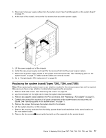
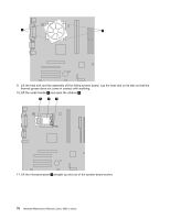
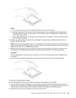
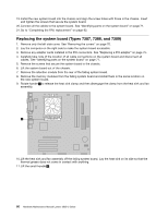
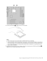
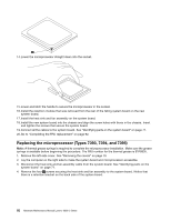
Notes: a. Your microprocessor and socket might look different than the one illustrated. b. Note the orientation of the notches on the microprocessor. This is important when reinstalling the microprocessor on the new system board. This is important when reinstalling the microprocessor on the new system board. c. Do not drop anything onto the microprocessor socket while it is exposed. The socket pins must be kept as clean as possible. 12. On the new system board, release the lever securing the microprocessor retainer and then pivot the retainer until it is fully open. Note: There will be a black plastic cover on the microprocessor retainer to protect the socket on the new system board. Remove the black plastic cover and place it on the microprocessor socket of the failing system board when you complete this procedure. 13. Holding the microprocessor with your fingers, position the microprocessor so that the notches on the microprocessor are aligned with the tabs in the microprocessor socket on the new system board. Important To avoid damaging the microprocessor contacts, do not tilt the microprocessor when installing it into the socket. 14. Lower the microprocessor straight down into the system board socket of the new system board. 15. Lower the microprocessor retainer. 16. Lock the retainer with the small handle to secure the microprocessor in the socket. 17. The new retention bracket has plastic one-way rings on the posts that insert into the rear of the new system board. Install the new retention bracket by aligning the posts on the module with the holes in the system board and pushing the posts through the holes until the retention bracket is secure. 18. Install the heat sink and fan assembly on the new system board. Chapter 8. Replacing FRUs (Types 7387, 7388, 7389, 7393, 7394, and 7395) 79
-
 1
1 -
2
-
3
-
4
-
5
-
6
-
7
-
8
-
9
-
10
-
11
-
12
-
13
-
14
-
15
-
16
-
17
-
18
-
19
-
20
-
21
-
22
-
23
-
24
-
25
-
26
-
27
-
28
-
29
-
30
-
31
-
32
-
33
-
34
-
35
-
36
-
37
-
38
-
39
-
40
-
41
-
42
-
43
-
44
-
45
-
46
-
47
-
48
-
49
-
50
-
51
-
52
-
53
-
54
-
55
-
56
-
57
-
58
-
59
-
60
-
61
-
62
-
63
-
64
-
65
-
66
-
67
-
68
-
69
-
70
-
71
-
72
-
73
-
74
-
75
-
76
-
77
-
78
-
79
-
 80
80 -
 81
81 -
 82
82 -
 83
83 -
 84
84 -
 85
85 -
 86
86 -
 87
87 -
 88
88 -
 89
89 -
 90
90 -
91
-
92
-
93
-
94
-
95
-
96
-
97
-
98
-
99
-
100
-
101
-
102
-
103
-
104
-
105
-
106
-
107
-
108
-
109
-
110
-
111
-
112
-
113
-
114
-
115
-
116
-
117
-
118
-
119
-
120
-
121
-
122
-
123
-
124
-
125
-
126
-
127
-
128
-
129
-
130
-
131
-
132
-
133
-
134
-
135
-
136
-
137
-
138
-
139
-
140
-
141
-
142
-
143
-
144
-
145
-
146
-
147
-
148
-
149
-
150
-
151
-
152
-
153
-
154
-
155
-
156
-
157
-
158
-
159
-
160
-
161
-
162
-
163
-
164
-
165
-
166
-
167
-
168
-
169
-
170
-
171
-
172
-
173
-
174
-
175
-
176
-
177
-
178
-
179
-
180
-
181
-
182
-
183
-
184
-
185
-
186
-
187
-
188
-
189
-
190
-
191
-
192
-
193
-
194
-
195
-
196
-
197
-
198
-
199
-
200
 |
 |
