Lenovo ThinkPad T430 Hardware Maintenance Manual - ThinkPad T430, T430i - Page 105
Base cover assembly and DC-in connector
 |
View all Lenovo ThinkPad T430 manuals
Add to My Manuals
Save this manual to your list of manuals |
Page 105 highlights
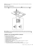
Attention: The microprocessor is extremely sensitive. When you service the microprocessor, avoid any kind of rough handling. Removal steps of microprocessor Rotate the head of the screw in the direction shown by the arrow 1 to release the lock, and remove the microprocessor 2 . After that, peel the mylar off from the microprocessor as shown by the arrow 3 . 2 3 1 4 When installing: Ensure that the mylar is attached to the microprocessor. Place the microprocessor in the microprocessor socket, and then rotate the head of the screw in the direction shown by the arrow 4 to secure the microprocessor. 1190 Base cover assembly and DC-in connector For access, remove these FRUs in order: • "1010 Battery pack" on page 66 • "1020 ExpressCard blank bezel" on page 67 • "1030 Serial Ultrabay Enhanced bay or blank bezel" on page 68 • "1040 Hard disk drive or solid-state drive" on page 69 • "1050 Memory module slot cover" on page 71 • "1060 Backup battery " on page 72 • "1080 PCI Express Mini Card for wireless WAN or mSATA solid-state drive" on page 73 • "1090 Keyboard" on page 78 • "1120 PCI Express Mini Card for wireless LAN/WiMAX" on page 83 • "1130 Keyboard bezel assembly, FPC cable, and Bluethooth daughter card" on page 84 Chapter 9. Removing or replacing a FRU 99
-
 1
1 -
2
-
3
-
4
-
5
-
6
-
7
-
8
-
9
-
10
-
11
-
12
-
13
-
14
-
15
-
16
-
17
-
18
-
19
-
20
-
21
-
22
-
23
-
24
-
25
-
26
-
27
-
28
-
29
-
30
-
31
-
32
-
33
-
34
-
35
-
36
-
37
-
38
-
39
-
40
-
41
-
42
-
43
-
44
-
45
-
46
-
47
-
48
-
49
-
50
-
51
-
52
-
53
-
54
-
55
-
56
-
57
-
58
-
59
-
60
-
61
-
62
-
63
-
64
-
65
-
66
-
67
-
68
-
69
-
70
-
71
-
72
-
73
-
74
-
75
-
76
-
77
-
78
-
79
-
80
-
81
-
82
-
83
-
84
-
85
-
86
-
87
-
88
-
89
-
90
-
91
-
92
-
93
-
94
-
95
-
96
-
97
-
98
-
99
-
 100
100 -
 101
101 -
 102
102 -
 103
103 -
 104
104 -
 105
105 -
 106
106 -
 107
107 -
 108
108 -
 109
109 -
 110
110 -
111
-
112
-
113
-
114
-
115
-
116
-
117
-
118
-
119
-
120
-
121
-
122
-
123
-
124
 |
 |
