Lenovo ThinkPad T430 Hardware Maintenance Manual - ThinkPad T430, T430i - Page 109
System board assembly, ExpressCard slot, and I/O sub card
 |
View all Lenovo ThinkPad T430 manuals
Add to My Manuals
Save this manual to your list of manuals |
Page 109 highlights
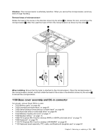
• "1190 Base cover assembly and DC-in connector" on page 99 Removal steps of magnesium structure frame 1 1 2 2 1 3 1 Step 1 2 Screw (quantity) M2 × 3 mm, wafer-head, nylon-coated (4) M2 × 9.5 mm, wafer-head, nylon-coated (2) Color Black Black Torque 0.181 Nm (1.85 kgfcm) 0.181 Nm (1.85 kgfcm) 1210 System board assembly, ExpressCard slot, and I/O sub card For access, remove these FRUs in order: • "1010 Battery pack" on page 66 • "1020 ExpressCard blank bezel" on page 67 • "1030 Serial Ultrabay Enhanced bay or blank bezel" on page 68 • "1040 Hard disk drive or solid-state drive" on page 69 • "1050 Memory module slot cover" on page 71 • "1080 PCI Express Mini Card for wireless WAN or mSATA solid-state drive" on page 73 • "1090 Keyboard" on page 78 • "1120 PCI Express Mini Card for wireless LAN/WiMAX" on page 83 • "1130 Keyboard bezel assembly, FPC cable, and Bluethooth daughter card" on page 84 • "1150 Speaker assembly" on page 89 • "1160 LCD unit" on page 91 • "1170 Thermal Fan assembly" on page 94 • "1180 Microprocessor" on page 98 • "1190 Base cover assembly and DC-in connector" on page 99 Important notices for handling the system board: When handling the system board, bear the following in mind: • The system board has an accelerometer, which can be broken by applying several thousands of G-forces. Note: Dropping a system board from a height of as little as 6 inches so that it falls flat on a hard bench can subject the accelerometer to as much as 6,000 G's of shock. • Be careful not to drop the system board on a bench top that has a hard surface, such as metal, wood, or composite. • If a system board is dropped, be sure to document the drop in a reject report, and replace the system board. • Avoid rough handling of any kind. • At every point in the process, be sure not to drop or stack the system board. Chapter 9. Removing or replacing a FRU 103
-
 1
1 -
2
-
3
-
4
-
5
-
6
-
7
-
8
-
9
-
10
-
11
-
12
-
13
-
14
-
15
-
16
-
17
-
18
-
19
-
20
-
21
-
22
-
23
-
24
-
25
-
26
-
27
-
28
-
29
-
30
-
31
-
32
-
33
-
34
-
35
-
36
-
37
-
38
-
39
-
40
-
41
-
42
-
43
-
44
-
45
-
46
-
47
-
48
-
49
-
50
-
51
-
52
-
53
-
54
-
55
-
56
-
57
-
58
-
59
-
60
-
61
-
62
-
63
-
64
-
65
-
66
-
67
-
68
-
69
-
70
-
71
-
72
-
73
-
74
-
75
-
76
-
77
-
78
-
79
-
80
-
81
-
82
-
83
-
84
-
85
-
86
-
87
-
88
-
89
-
90
-
91
-
92
-
93
-
94
-
95
-
96
-
97
-
98
-
99
-
100
-
101
-
102
-
103
-
 104
104 -
 105
105 -
 106
106 -
 107
107 -
 108
108 -
 109
109 -
 110
110 -
 111
111 -
 112
112 -
 113
113 -
 114
114 -
115
-
116
-
117
-
118
-
119
-
120
-
121
-
122
-
123
-
124
 |
 |
