Lenovo ThinkServer RD120 User Guide - Page 89
Installing, cover, Connecting, cables
 |
View all Lenovo ThinkServer RD120 manuals
Add to My Manuals
Save this manual to your list of manuals |
Page 89 highlights
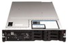
4. Install the server in a rack. See the Rack Installation Instructions that come with the server for complete rack installation and removal instructions. 5. To attach peripheral devices and connect the power cords, see "Connecting the cables." Attention: In a dc power environment, only trained service personnel other than Lenovo service technicians are authorized to connect or disconnect power to the dc power supply. See the documentation that comes with each dc power supply. Installing the cover To install the cover, complete the following steps: 1. Place the cover-release latch 1 in the open (up) position. 2. Insert the bottom tabs of the top cover into the matching slots in the server chassis. 3. Press down on the cover-release latch to lock the cover in place. 4. Slide the server into the rack. Connecting the cables The following illustrations show the locations of the input and output connectors on the front and rear of the server. Front view 1 USB 5 connector 2 USB 6 connector 3 Video connector Chapter 2. Installing optional devices 75
-
 1
1 -
2
-
3
-
4
-
5
-
6
-
7
-
8
-
9
-
10
-
11
-
12
-
13
-
14
-
15
-
16
-
17
-
18
-
19
-
20
-
21
-
22
-
23
-
24
-
25
-
26
-
27
-
28
-
29
-
30
-
31
-
32
-
33
-
34
-
35
-
36
-
37
-
38
-
39
-
40
-
41
-
42
-
43
-
44
-
45
-
46
-
47
-
48
-
49
-
50
-
51
-
52
-
53
-
54
-
55
-
56
-
57
-
58
-
59
-
60
-
61
-
62
-
63
-
64
-
65
-
66
-
67
-
68
-
69
-
70
-
71
-
72
-
73
-
74
-
75
-
76
-
77
-
78
-
79
-
80
-
81
-
82
-
83
-
 84
84 -
 85
85 -
 86
86 -
 87
87 -
 88
88 -
 89
89 -
 90
90 -
 91
91 -
 92
92 -
 93
93 -
 94
94 -
95
-
96
-
97
-
98
-
99
-
100
-
101
-
102
-
103
-
104
-
105
-
106
-
107
-
108
-
109
-
110
-
111
-
112
-
113
-
114
-
115
-
116
-
117
-
118
 |
 |
