LiftMaster Dial Code Dial Code VF Series Manual
LiftMaster Dial Code Manual
 |
View all LiftMaster Dial Code manuals
Add to My Manuals
Save this manual to your list of manuals |
LiftMaster Dial Code manual content summary:
- LiftMaster Dial Code | Dial Code VF Series Manual - Page 1
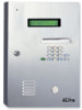
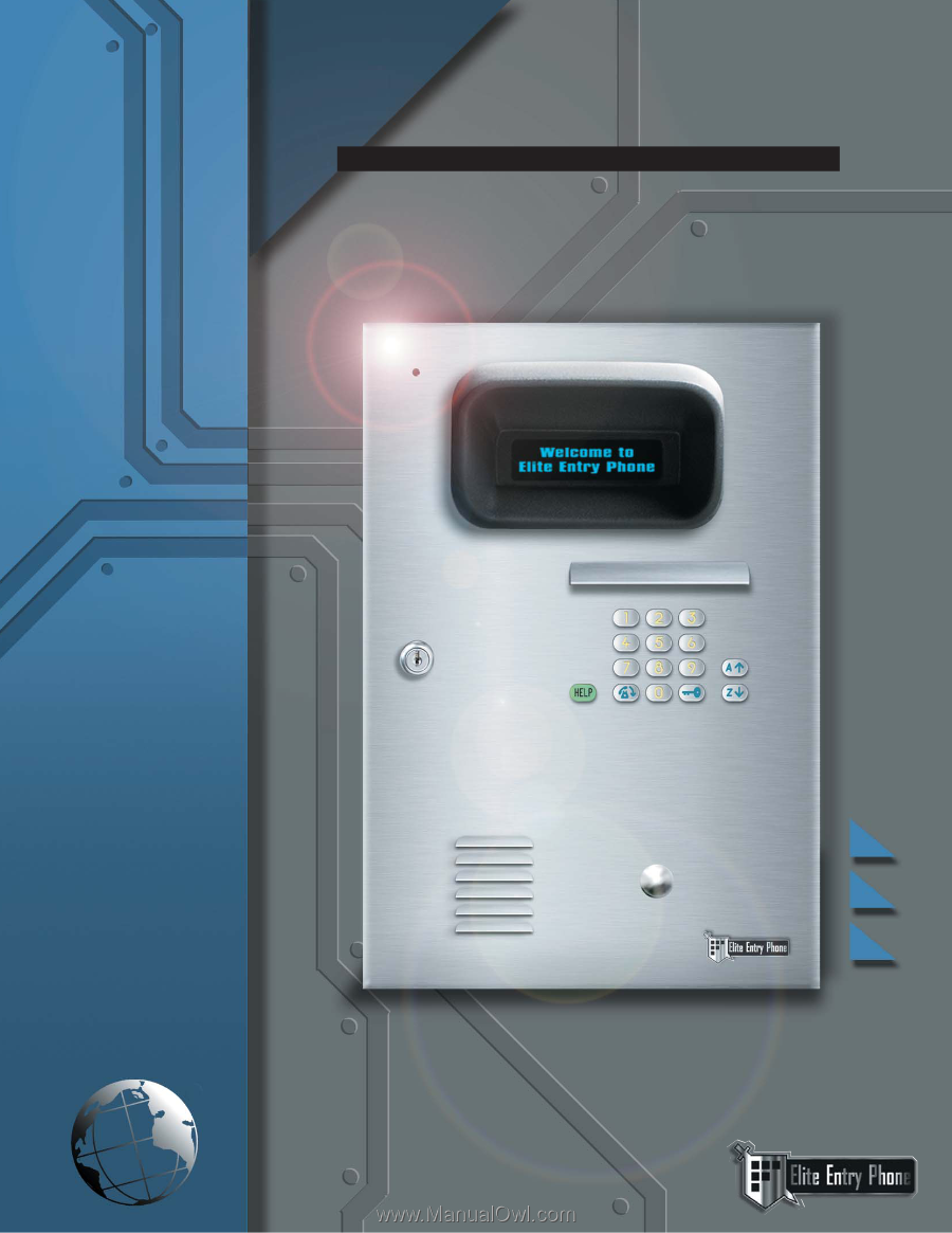
DIAL CODE VF SERIES OWNER S MANUAL Telephone entry system with two line super bright vf display VISIT US ON THE WEB www.eliteentryphone.com ® MADE IN USA - LiftMaster Dial Code | Dial Code VF Series Manual - Page 2
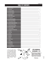
Information Transmitter/Card Programming Area Codes Utility Codes Password Clock Timer Strike Time Talk Time Report Printing Greeting Volume Adjust Backup Memory Error Messages Parts List & Diagram Approvals © 1997 BY ELITE ENTRY PHONE ALL RIGHTS RESERVED. NO PART OF THIS MANUAL MAY BE REPRODUCED IN - LiftMaster Dial Code | Dial Code VF Series Manual - Page 3
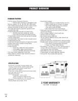
5 hrs. • Battery enables dial out, program, & display. • Non-Volatile SRAM memory has unlimited write cycles (unlike EEPROM). • Non-Volatile Real Time Clock/Calendar. • High quality voice communication system with background noise filtering. • Voice messages (digital) to help & guide user. • Volume - LiftMaster Dial Code | Dial Code VF Series Manual - Page 4
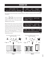
names listed in the Entry Phone's electronic directory as shown in (fig c.) The names are listed in alphabetical order by last name. fairbanks, george CODE: 012 (fig c.) When the desired name is found, enter the corresponding 3-digit code. The system will dial the number assigned to the tenant - LiftMaster Dial Code | Dial Code VF Series Manual - Page 5
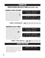
within the time zone for entry, the display will inform the user and access will not be allowed (fig d.) * ACCESS GRANTED * please enter (fig c.) * ACCESS DENIED * not in access period (fig d.) EXAMPLE - UTILITY CODE 8716 = 8 7 16 SCREEN SAVER MODE If the Dial Code System is inactive for 15 - LiftMaster Dial Code | Dial Code VF Series Manual - Page 6
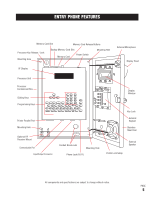
ENTRY PHONE FEATURES Memory Card Slot Memory Card Release Buttons Processor Key Release / Lock Mounting Hole Backup Memory Card Slot Memory Card Power Switch Mounting Hole VF Display External Microphone Display Hood Processor Unit Processor Containment Box Dialing Keys Programming Keys - LiftMaster Dial Code | Dial Code VF Series Manual - Page 7
to help guide the user. 4 EXTERNAL SPEAKER 5 DISPLAY HOOD - Reduces reflections and direct sunlight. 7 6 DISPLAY WINDOW - Heavy-duty, 3/8" thick protective lens. 8 7 DIALING KEYS LIGHT - Lights up dialing keys for easy visibility. 9 8 PHONE DIALING KEYS - Used to dial residents / keycodes - LiftMaster Dial Code | Dial Code VF Series Manual - Page 8
. 16 CARD SLOTS - Front slot holds Backup Memory or RF Card, back slot holds Main Memory Card. 17 16 15 18 14 17 MEMORY CARD - Stores all programmed information. 18 SUPER BRIGHT VACUUM FLUORESCENT DISPLAY SCREEN - Displays information and instructions, two lines at a time. 19 DIRECTION KEYS - LiftMaster Dial Code | Dial Code VF Series Manual - Page 9
lines through the appropriate holes for connecting to the Processor Unit. 2 1/8" 1 1/16" 14 9/16" 1 7/8" 16 7/16" PAGE 8 11 1/4 3 3/16 NOTE: Be sure to install the Entry Phone at normal eye level All components and specifications are subject to change without notice. - LiftMaster Dial Code | Dial Code VF Series Manual - Page 10
WIRING DIAGRAM ELITE ENTRY PHONE "DEDICATED" TELEPHONE LINE USOC RJ11C AWG MAX. DISTANCE 24 170' 22 280' 20 450' 18 700' 16 1100' 12VAC 40VA see chart above for distance BLACK/WHITE VEHICULAR GATE 2 YELLOW WIRES ENTRY 1 2 BLUE WIRES ENTRY 2 LOCK CONDUIT PEDESTRIAN GATE ENTRY DOOR - LiftMaster Dial Code | Dial Code VF Series Manual - Page 11
POSTAL LOCK SWITCH ASSEMBLY MOUNTING HOLES (MOUNT WITH POSTAL LOCK ON ENTRY PHONE FRONT PANEL) STAINLESS STEEL FRONT PANEL (Retain nuts and washers relay) at the 15 pin input/output connector. Note that polarity or color coding is not required. As example: If you wish to activate the door using - LiftMaster Dial Code | Dial Code VF Series Manual - Page 12
pedestrian gate or door. 6 12 VAC: Power supply to the Entry Phone. 7 MICROPHONE: Pre-installed microphone input. 8 TELEPHONE LINE: Standard USOC RJ11C phone line (included) to be connected to standard phone jack. NOTE: Telephone line used for phone entry system must be a dedicated line. PAGE 11 - LiftMaster Dial Code | Dial Code VF Series Manual - Page 13
PORT CONNECTORS Entry Phone Processor OPTIONAL Parallel Printer Port connection see page 28 3 USOC RJ11C Telephone Line (included (See Receiver Connection Manual.) 2 RS485: Connect to corresponding RS485 terminals (-, +, GND) of remote security devices. 3 TELEPHONE LINE: Standard USOC RJ11C - LiftMaster Dial Code | Dial Code VF Series Manual - Page 14
RS-485 CONNECTION EXAMPLE RF Receiver wires BLACK GREEN WHITE LOCAL RF RECEIVER 123 456 789 *0 # KEYPAD RS 485 REMOTE DEVICE 1 RS485 wires RS485 (-) (blue) RS485 (+) (brown) RS485 GND (yellow) STAND-ALONE RECEIVER RS 485 REMOTE DEVICE 2 CARD READER RS 485 REMOTE DEVICE 3 UNIVERSAL INTERFACE - LiftMaster Dial Code | Dial Code VF Series Manual - Page 15
rotary switches on the device. (Refer to specific RS 485 Instruction sheets). Configuration #2 "Star" wiring configuration • Maximum number of wire runs allowed is 7 • Maximum distance from the last RS 485 device (per wire run) to the Entry Phone is 4000 Ft. Turn Terminator Switch "ON" for Last - LiftMaster Dial Code | Dial Code VF Series Manual - Page 16
an information screen is accessible on all Dial Code systems for easy reference. Turn power off and insert Memory Card in Main Memory Slot. Turn power on and the information screen should display as seen in (fig e.) MEMORY CAPACITY DIAL CODE VF-250 REV. 1.00_ (fig c.) SOFTWARE VERSION NUMBER PAGE 15 - LiftMaster Dial Code | Dial Code VF Series Manual - Page 17
black & white wires to the 12V (AC or DC) transformer per all local codes & standards. STEP 3 Plug in the transformer. Test the phone for normal function. the power on. WARNINGS AND PRECAUTIONS A PAGE 16 250 B A. The Entry Phone is only water resistant when the Stainless Steel Door is closed and - LiftMaster Dial Code | Dial Code VF Series Manual - Page 18
PROGRAMMING THE PROCESSOR ENTERING THE PROGRAM MODE When the Processor unit is turned on and the button is pressed, the screen will display: TO ENTER PROG MODE, type password >____ Type in the factory present password (7777). Press will display: . The Program Selection Screen SELECT PROG MODE: - LiftMaster Dial Code | Dial Code VF Series Manual - Page 19
Password ( recommended ) Program System Clock and Seven Day Timers Program relay output time ( for 2 relays ) Program length of Talk Time Program setup of different report printing Program custom Welcome Screen Program Volume level Backup of memory card page 19-21 page 22 page 23 pages 24-26 page - LiftMaster Dial Code | Dial Code VF Series Manual - Page 20
can edit the name by simply typing over it. Press the key to complete the entry. You may also use the keys to move the cursor within a code. Tenant code 005 LastNAME,First jones, robert_ 005 PHONE NUMBER: _-___-496-2634 Tenant name (example - fig c.) (example - fig d.) 4 STEP Type in the - LiftMaster Dial Code | Dial Code VF Series Manual - Page 21
/CARD PROGRAMMING 6 STEP To complete entry, press the key to return to memory card installation section of manual) 7 STEP Use keys to view and program up to 10 transmitter or card codes associated to the directory code. To program a transmitter or card code, you may enter the code manually - LiftMaster Dial Code | Dial Code VF Series Manual - Page 22
can change the prefix to any number. To choose 8, 9, or 10-digit dialing, when no prefix is needed, press while in the prefix field. Then type the required number of digits in the area code field followed by the phone number. Press the key to continue with the entry as described on Page 19. To - LiftMaster Dial Code | Dial Code VF Series Manual - Page 23
assigned to "Utility Companies" such as delivery, telephone, construction companies, water, power, etc. These utilities can use their individual code to access the premises within the time zone that you program. Each system, no matter what the memory capacity, is equipped with 60 available Utility - LiftMaster Dial Code | Dial Code VF Series Manual - Page 24
message. IMPORTANT NOTE: While in the help screens, programming will be disabled. To continue programming, press the button to exit the help screens first. PAGE 23 - LiftMaster Dial Code | Dial Code VF Series Manual - Page 25
Use the keys to scroll between the three different menu choices (fig b.). Select the number of your choice or press the key cursor. Press the key to enter your input.(fig c.) DATE>02-11-96 time>07:31am p=pm (fig c.) Use the entry. (fig e.) daylight savings>y (Y)yes (N)no (fig e.) PAGE 24 - LiftMaster Dial Code | Dial Code VF Series Manual - Page 26
Press 2 to program Gate Timers Menu. Press 3 to program the Door Timers Menu. setup new timers> N view/edit timers> See next page for instructions USE ARROWS TO VIEW / PROGRAM INDIVIDUAL TIME ZONES Use to view and program timer(s) for Sunday through Saturday. Move the cursor to time and type - LiftMaster Dial Code | Dial Code VF Series Manual - Page 27
Menu Press 3 to program the Door Timers Menu setup new timers> N view/edit timers> PRESS (N) TO PROGRAM SETS OF TIME ZONES See previous page for instructions Program timers 1 & 2 for any day of the week (fig d.) Press N to turn timer 1 ON or press F to turn timer 1 OFF. Press the key. Type the - LiftMaster Dial Code | Dial Code VF Series Manual - Page 28
key to enter your selection. DOOR STRIKE TIME: [01-99] 10 seconds GATE STRIKE TIME: [01-12] 05 seconds (fig c.) (fig d.) DOOR NAME/LOCATION south entry door GATE NAME/LOCATION north side gate (fig e.) (fig f.) For either the Gate or Door Strike Time, you may now type in a name and location - LiftMaster Dial Code | Dial Code VF Series Manual - Page 29
print. There are four options to print; all tenants names in order (fig b.), All tenants codes in order (fig c.), Utility Keycodes (fig d.), or 7-Day Timer settings (fig e.). NOTE ASCII format, check the owners manual that came with your printer or call your printer's manufacturer. PAGE 28 - LiftMaster Dial Code | Dial Code VF Series Manual - Page 30
Selection Screen (fig a.), Press the G key. Type the name of the facility and press the key to complete your entry. The system will automatically center your entry on the Welcome screen.(fig b.) SELECT PROG MODE: (G)greeting (fig a.) FACILITY NAME: woodbridge meadows (fig b.) VOLUME ADJUST Use the - LiftMaster Dial Code | Dial Code VF Series Manual - Page 31
than the Main Memory card being backed up. The screens will display when the cards were last updated. (fig c.) and (fig d.) Use the keys to scroll through the information. SELECT PROG MODE: (V)volume (B)backup (fig b.) MAIN card updated on 05-15-96 03:50am (fig c.) BACKUP card updated 02-11-96 - LiftMaster Dial Code | Dial Code VF Series Manual - Page 32
for instructions. 949-580-1700 *IMPORTANT NOTE: In order to charge the battery in the Dial Code System, the processor must be plugged in to the transformer and the processor MUST BE ON. If the power is off on the processor, the battery will not be charging. welcome to C elite entry phone - LiftMaster Dial Code | Dial Code VF Series Manual - Page 33
PART # T013 T014 T018 T025 T026 T028 T029 T031 T034 DESCRIPTION Mobile Power Connection Kit (Includes: transformer and 15 pin connector) External Box Processor Key For Internal / External Lock Kit For Keypad Light External Box Assy. (VF) (No Processor, Postal Lock or Memory Card) All components - LiftMaster Dial Code | Dial Code VF Series Manual - Page 34
Canada (IC) Notice Instruction with the instructions, may Canada degradation of service in some telephone lines and internal metallic water pipe system Number (REN) assigned to each terminal device provides an indication of the maximum number of terminals allowed to be connected to the telephone
-
 1
1 -
 2
2 -
 3
3 -
 4
4 -
 5
5 -
 6
6 -
 7
7 -
8
-
9
-
10
-
11
-
12
-
13
-
14
-
15
-
16
-
17
-
18
-
19
-
20
-
21
-
22
-
23
-
24
-
25
-
26
-
27
-
28
-
29
-
30
-
31
-
32
-
33
-
34
 |
 |
DIAL CODE VF SERIES
O
W
N
E
R
S
M
A
N
U
A
L
Telephone entry system with two line super bright vf display
www.eliteentryphone.com
VISIT US ON THE WEB
MADE IN USA
®