LiftMaster Dial Code Dial Code VF Series Manual - Page 9
Mounting Installation, FOR INSTALLATION
 |
View all LiftMaster Dial Code manuals
Add to My Manuals
Save this manual to your list of manuals |
Page 9 highlights
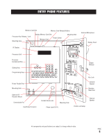
MOUNTING INSTALLATION MOUNTING HOLES 1/4" dia. 1" 1.5" 8 3/4" WALL 2 1/2" 14 1/2" 6 3/4" 4 1/2" CONDUIT KNOCK-OUTS 7/8" dia. FOR INSTALLATION ON WALL Remove the Processor Unit from the Processor Containment Box and bolt the Processor Containment Box to recess in wall using the four mounting holes. Feed the power and phone lines through the appropriate holes for connecting to the Processor Unit. 2 1/8" 1 1/16" 14 9/16" 1 7/8" 16 7/16" PAGE 8 11 1/4 3 3/16 NOTE: Be sure to install the Entry Phone at normal eye level All components and specifications are subject to change without notice.
-
 1
1 -
2
-
3
-
 4
4 -
 5
5 -
 6
6 -
 7
7 -
 8
8 -
 9
9 -
 10
10 -
 11
11 -
 12
12 -
 13
13 -
 14
14 -
15
-
16
-
17
-
18
-
19
-
20
-
21
-
22
-
23
-
24
-
25
-
26
-
27
-
28
-
29
-
30
-
31
-
32
-
33
-
34
 |
 |

PAGE
8
MOUNTING INSTALLATION
WALL
MOUNTING HOLES
1/4”
dia.
CONDUIT KNOCK-OUTS
7/8”
dia.
2
1/8
”
1
1/
16
”
8
3/
4
”
14
1/
2
”
6
3/
4
”
4
1/
2
”
14
9/
16
”
2
1/
2
”
1
7/
8
”
FOR INSTALLATION
ON
WALL
Remove the Processor
Unit from the Processor
Containment Box and
bolt the Processor
Containment Box to
recess in wall using the
four mounting holes.
Feed the power and
phone lines through the
appropriate holes for
connecting to the
Processor Unit.
NOTE:
Be sure to install the Entry Phone at normal eye level
16
7/
16
”
11
1/
4
3
3/
16
All components and specifications are subject to change without notice.
1.5
”
1
”