LiftMaster Dial Code Dial Code VF Series Manual - Page 10
Wiring Diagram, OR
 |
View all LiftMaster Dial Code manuals
Add to My Manuals
Save this manual to your list of manuals |
Page 10 highlights
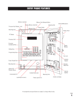
WIRING DIAGRAM ELITE ENTRY PHONE "DEDICATED" TELEPHONE LINE USOC RJ11C AWG MAX. DISTANCE 24 170' 22 280' 20 450' 18 700' 16 1100' 12VAC 40VA see chart above for distance BLACK/WHITE VEHICULAR GATE 2 YELLOW WIRES ENTRY 1 2 BLUE WIRES ENTRY 2 LOCK CONDUIT PEDESTRIAN GATE ENTRY DOOR OR MASTER GATE OPERATOR (STRIKE OPEN INPUT) ACCESS DOOR WXY 9 OR JKL 5 Connect the two yellow wires to the main vehicular gate operator or door. The gate/door will be activated by either pressing 9 from the residents side, or by using a utility keycode, individual keycode or optional RF transmitter from Entry Phone side. (Refer to page 12 & 13) Connect the two blue wires to the secondary gate or door. The gate/door will only be activated from the residents side by pressing 5. (Refer to page 27 to adjust the strike times). PAGE 9
-
 1
1 -
2
-
3
-
4
-
 5
5 -
 6
6 -
 7
7 -
 8
8 -
 9
9 -
 10
10 -
 11
11 -
 12
12 -
 13
13 -
 14
14 -
 15
15 -
16
-
17
-
18
-
19
-
20
-
21
-
22
-
23
-
24
-
25
-
26
-
27
-
28
-
29
-
30
-
31
-
32
-
33
-
34
 |
 |
