LiftMaster GH GH LOGIC VERSION 2 Manual
LiftMaster GH Manual
 |
View all LiftMaster GH manuals
Add to My Manuals
Save this manual to your list of manuals |
LiftMaster GH manual content summary:
- LiftMaster GH | GH LOGIC VERSION 2 Manual - Page 1
Maintenance Cycle Counter. An LED on the 3-button station will signal when the set number of cycles is reached or when the opener requires immediate service. 2 YEAR WARRANTY Serial # (located on electrical box cover) Installation Date Wiring Type NOT FOR RESIDENTIAL USE 41B6 LISTED DOOR OPERATOR - LiftMaster GH | GH LOGIC VERSION 2 Manual - Page 2
Controls 9 Mounting Instructions 9 Optional Control Mounting 9 Optional Control Wiring 28 CLUTCH ADJUSTMENT Clutch Parts 10 Clutch Adjustment 10 BRAKE ADJUSTMENT Brake Parts 10 WIRING DIAGRAMS 1 PH Wiring 11 3 PH Wiring 12 1 PH Wiring w/Contactor 13 STANDARD PROGRAMMING Wiring Type 14 - LiftMaster GH | GH LOGIC VERSION 2 Manual - Page 3
open override. See pages 14 and 15 for optional wiring types and operating modes. LIMIT ADJUST Linear driven, fully adjustable screw type cams. Adjustable to 30 feet. MECHANICAL DRIVE REDUCTION 40:1 Reduction Heavy duty bronze worm gear reducer OUTPUT SHAFT SPEED:.....43 R.P.M. DOOR SPEED 4 - 10 - LiftMaster GH | GH LOGIC VERSION 2 Manual - Page 4
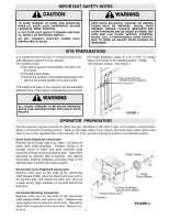
SION AND CAN CAUSE SERIOUS PERSONAL INJURY. CALL A PROFESSIONAL DOOR SERVICE- MAN TO MOVE OR ADJUST DOOR SPRINGS OR HARDWARE. CAUTION SITE PREPARATIONS It is imperative that the wall or mounting surface provide adequate support for the operator. This surface must: a) Be rigid to prevent play - LiftMaster GH | GH LOGIC VERSION 2 Manual - Page 5
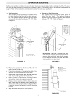
on page 3. Refer to the illustration and instructions below that suits your application. 1a. Wall Mounting The operator should generally be installed below the door shaft, and as close to the door as possible. The optimum distance between the door shaft and operator drive shaft is between 12" - 15 - LiftMaster GH | GH LOGIC VERSION 2 Manual - Page 6
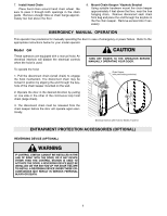
nec- W essary. EMERGENCY MANUAL OPERATION This operator has provisions for manually operating the door in case of emergency or power failure. Refer to the appropriate instructions below for your model operator. Model GH These operators are equipped with a manual hoist. An electrical interlock - LiftMaster GH | GH LOGIC VERSION 2 Manual - Page 7
device to the LiftMaster Authorized Dealer. operator, refer to the wiring diagram on pages 11-13. See field connection terminals identified as Reversing Device. If not pre-installed by the door manufacturer, mount the sensing edge on the door according to the instructions pro- vided with - LiftMaster GH | GH LOGIC VERSION 2 Manual - Page 8
electrical box is only to be accessed by trained "LIFTMASTER" technicians. If service is required contact your local LIFTMASTER dealer. Do not install any wiring or attempt to run the operator without consulting the wiring diagram. Install the optional Reversing Edge before proceeding with the - LiftMaster GH | GH LOGIC VERSION 2 Manual - Page 9
On all models with B2 control wiring, a terminal bracket marked R1 R2 R3 is located on the outside of the electrical enclosure. Any commercial type LiftMaster brand receiver may be mounted to this bracket. The operator will then open a fully closed door, close a fully open door, stop an opening door - LiftMaster GH | GH LOGIC VERSION 2 Manual - Page 10
little tension on the clutch spring. 3. Tighten clutch nut gradually until there is just enough tension to permit the operator to move the door smoothly but to allow the clutch to slip if the door is obstructed. When the clutch is properly adjusted, it should generally adjusted, it should generally - LiftMaster GH | GH LOGIC VERSION 2 Manual - Page 11
LOGIC CONTROL (VER. 2.0) 1 PHASE WIRING DIAGRAM 1837-1 230 VOLT MOTOR CONNECTION NOTE: Contactor 1 PH / 3 PH jumper should be in 1 PH position. 115 VOLT MOTOR CONNECTION Note: 1) See Ownerʼs Manual for Dip Switch Functions and Programming Procedures 2) TO REVERSE MOTOR DIRECTION 115 VOLTS: ALWAYS - LiftMaster GH | GH LOGIC VERSION 2 Manual - Page 12
LOGIC CONTROL (VER. 2.0) 3 PHASE WIRING DIAGRAM 1837-3 380/460 VOLT MOTOR CONNECTION NOTE: Contactor 1 PH / 3 PH jumper should be in 3 PH position. 230 VOLT MOTOR CONNECTION Notes: 1) See Ownerʼs Manual for Dip Switch Functions and Programming Procedures 2) TO REVERSE MOTOR DIRECTION: INTERCHANGE - LiftMaster GH | GH LOGIC VERSION 2 Manual - Page 13
LOGIC CONTROL (VER. 2.0) 1 PH WIRING DIAGRAM W/ CONTACTOR1842-1 NOTE: Contactor 1 PH / 3 PH jumper should be in 1 PH position. 115 VOLT MOTOR CONNECTION Note: 1) See Ownerʼs Manual for Dip Switch Functions and Programming Procedures 2) TO REVERSE MOTOR DIRECTION 115 & 230 VOLTS: INTERCHANGE PURPLE & - LiftMaster GH | GH LOGIC VERSION 2 Manual - Page 14
switch adjustment instructions. Logic Control Pushbuttons Open, Close, Stop Open, Close and Stop buttons are mounted directly on the Logic Control board. This will provide easy programming ability and door control at the electrical box. Either the stop control or a jumper must be wired between - LiftMaster GH | GH LOGIC VERSION 2 Manual - Page 15
OPTIONS To use the operator in any of the Failsafe wiring modes, or Timer To Close wiring modes (TS, T, FSTS), a LiftMaster self monitoring safety device must be installed. Recommended LiftMaster Self Monitoring Safety Devices: CPS-L NEMA 1 Direct Connect Eyes CPS-LN4 NEMA 4 Direct Connect Eyes - LiftMaster GH | GH LOGIC VERSION 2 Manual - Page 16
over and wait about ⁄ to fi second between pressing "open" and "learn". 4. Return the dip switches to your regular wiring type (C2, B2, etc.) and close the door. Note: LiftMaster 2.0 Logic operators are designed to work in most cases without adjusting the RPM sensor. It is still recommended to set - LiftMaster GH | GH LOGIC VERSION 2 Manual - Page 17
fully providing longer door and operator life. 1 2 3 4 OFF To Program: 1. Close the door. 2. Set dip switches to "set mid stop". 3. Press open (the door will begin moving) 4. Press stop when the desired mid stop height is reached. 5. Return the dip switches to the desired wiring type (C2,B2 - LiftMaster GH | GH LOGIC VERSION 2 Manual - Page 18
Close to be activated by the Single Button Control (terminal 1) only. T wiring mode allows the door to attempt to close only one time for safety purposes. Adjusting your red/green warning lights Feature: The logic board can adjust the amount of time that a warning light will flash before the Timer - LiftMaster GH | GH LOGIC VERSION 2 Manual - Page 19
LOGIC 2.0 PCB BOARD ILLUSTRATION RPM Learn Button (see page 16) Power Wiring Terminal Block (see pages 8-9) Dip Switch (see pages 8-9) Control Wiring Terminal Block (see pages 8-9) Open, Close, Stop Buttons 19 - LiftMaster GH | GH LOGIC VERSION 2 Manual - Page 20
a) Operator control station is wired wrong b) Motor is malfunctioning RESOLUTION Reset the RPM sensor. Also verify that the software is version 260 or better. Order replacement chips from Parts and Service. Reset the Maximum Run Timer Reset the mid-stop by programming it to be at the open limit - LiftMaster GH | GH LOGIC VERSION 2 Manual - Page 21
wiring type. STEP 3: Relearn RPM. Because factory default is set without a door attached to the operator, factory default setting is not a preferred status. 1. Start with the door closed and set all Dip switches to the off position. 2. Press open then press and hold the "learn" button on the Logic - LiftMaster GH | GH LOGIC VERSION 2 Manual - Page 22
procedures. Do not lubricate motor. Motor bearings are rated for continuous operation. Do not lubricate clutch or V-belt. Inspect and service whenever a malfunction is observed or suspected. CAUTION: BEFORE SERVICING, ALWAYS DISCONNECT OPERATOR FROM POWER SUPPLY. HOW TO ORDER REPAIR PARTS OUR LARGE - LiftMaster GH | GH LOGIC VERSION 2 Manual - Page 23
ILLUSTRATED PARTS - ELECTRICAL BOX S6 S5 S2 12 S7 S1 S8 S4 S9 5 S3 L3 L1 10 6 L5 7 L8 L6 L2 L9 L8 2 11 1 3 L7 4 8 9 L2 L6 L4 4 23 - LiftMaster GH | GH LOGIC VERSION 2 Manual - Page 24
box, motor or brake components be sure to match model number of your unit to kit number below to ensure proper voltage requirements. Optional modifications and/or accessories included with your operator may add or remove certain components from these lists. Please consult a parts and service - LiftMaster GH | GH LOGIC VERSION 2 Manual - Page 25
4 5 1 6 B10 D4 D11 D9 D12 D15 D16 D8 D5 D15 D13 D3 D7 D6 D1 D2 D10 H15 H9 H6 ILLUSTRATED PARTS - MODEL GH 25 2 3 G2 D13 H13 H12 G1 H9 H4 H5 H15 B9 D15 D14 H15 H2 H9 H5 B7 H15 B3 B2 G3 H3 H8 B1 B4 B6 B5 H11 H7 B8 B11 H14 H1 H10 - LiftMaster GH | GH LOGIC VERSION 2 Manual - Page 26
12584 K75-12585 OPERATOR(S) 115 Volt Models 230-460 Volt Models ITEM B1 B2 B3 B4 B5 B6 B7 B8 B9 B10 B11 PART # 07-10179 10-10190-C 10-10191 11-16094 11-16095 18-10194 31-10186 75-10184 75-11034 75-11035 75-11036 80-9001 87-P-062 DESCRIPTION Brake Hub Brake Release Lever Brake Disk Spring Cup for - LiftMaster GH | GH LOGIC VERSION 2 Manual - Page 27
NOTES 27 - LiftMaster GH | GH LOGIC VERSION 2 Manual - Page 28
DOOR OPERATOR 3 BUTTON STATION OR 3 POSITION KEYSWITCH WITH SPRING RETURN TO CENTER AND STOP BUTTON STANDARD 10 7 6 4 5 2 OR MORE 10 7 6 4 5 KEY LOCKOUT 10 7 6 4 5 (RED) Alert LED (WHITE) Open Close Stop (RED) Alert LED (WHITE) Open Close Stop Open Close Stop (RED) Alert LED (WHITE) Open
-
 1
1 -
 2
2 -
 3
3 -
 4
4 -
 5
5 -
 6
6 -
 7
7 -
8
-
9
-
10
-
11
-
12
-
13
-
14
-
15
-
16
-
17
-
18
-
19
-
20
-
21
-
22
-
23
-
24
-
25
-
26
-
27
-
28
 |
 |
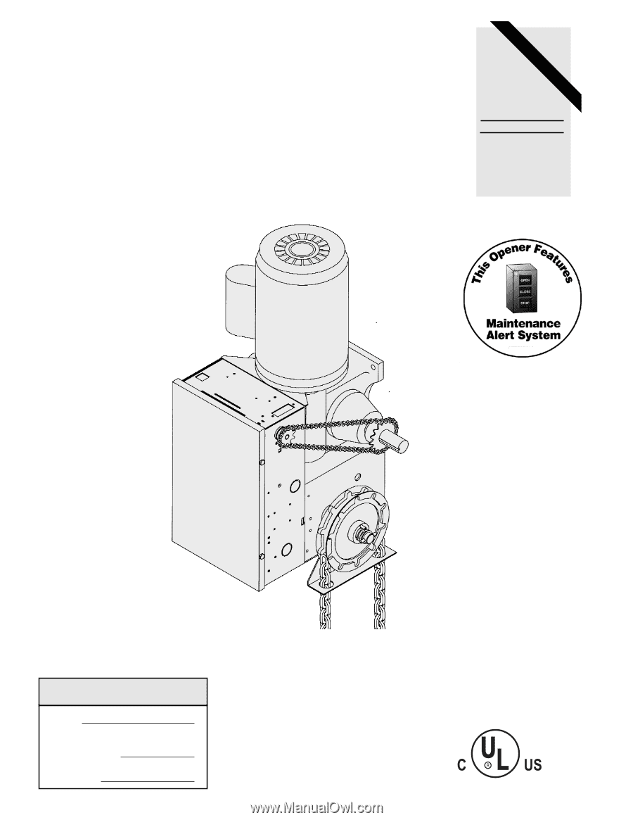
OWNER'S MANUAL
MODEL GH
LOGIC CONTROL (VER. 2.0)
INDUSTRIAL DUTY DOOR OPERATOR
LOGIC CONTROL
L
C2 Wiring
FACTORY SET
See pages 14 and 15
for other wiring
configurations
Serial #
(located on electrical box cover)
Installation Date
Wiring Type
2
YEAR
WARRANTY
PATENT PENDING
The Maintenance Alert System
allows the installer to set an internal
Maintenance Cycle Counter.
An LED
on the 3-button station will signal when
the set number of cycles is reached or
when the opener requires immediate
service.
TM
NOT FOR RESIDENTIAL USE
LISTED
DOOR
OPERATOR
41B6