LiftMaster GH GH LOGIC VERSION 2 Manual - Page 21
Step 3, Step 2
 |
View all LiftMaster GH manuals
Add to My Manuals
Save this manual to your list of manuals |
Page 21 highlights
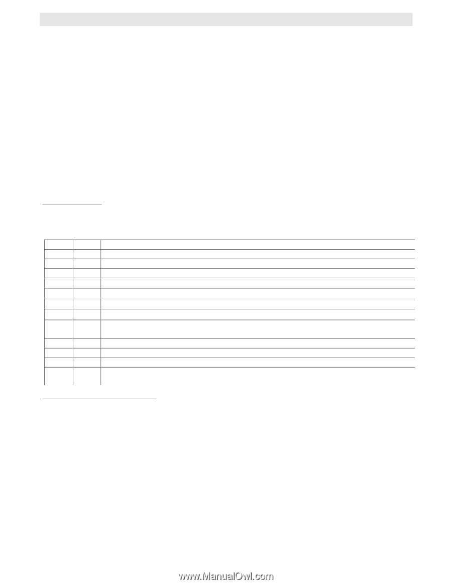
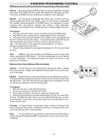
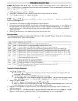
TROUBLE SHOOTING STEP 2: To "unlearn" the photo eyes. The latest software automatically learns if direct connect photo eyes (CPS-L or CPS-LN4) are attached during the first open cycle of operation. If they are disconnected at some point after this, they must be unlearned. 1. Set the dip switches to set Timer To Close. 2. Press Open 2 times then Close 2 times and then Stop 2 times (order is not specific). 3. Return the dip switches to the desired wiring type. STEP 3: Relearn RPM. Because factory default is set without a door attached to the operator, factory default setting is not a preferred status. 1. Start with the door closed and set all Dip switches to the off position. 2. Press open then press and hold the "learn" button on the Logic board (see picture) until the door reaches the full open position. You should see the Learn LED turn off after pressing the learn button; it will turn back on about 5 seconds later. If the LED did not cycle, start over and wait about ⁄ to fi second between pressing "open" and "learn". 3. Return the dip switches to your regular wiring mode and close the door. Diagnostic LEDs There should always be 3 green LEDs activated (24 VAC, 5 VDC, and STOP Button). Check for this first then proceed to check the status of the remaining LEDs LED 24VAC 5VDC Diag REV COLOR MEANING OF EACH LED Green Indicates that 24 VAC is being received from the transformer Green Indicates that 5VDC is being generated for the logic board to use Red Indicates that the MAS LED on the 3 button control station is being turned on. Red Indicates a short between common and terminal 8. Pressing the edge should turn ON this LED Open Red Close Red Indicates a short between common and terminal 7. Pressing the open button should turn ON this LED Indicates a short between common and terminal 6. Pressing the close button should turn ON this LED Stop Green Indicates a short between Common and terminal 5. Pressing the stop button should turn OFF this LED. SBC OLS CLS SLS Learn Red Red Red Red Amber Indicates a short between Common and terminal 1. Pressing the Single Button Control station should turn ON this LED. Indicates the Open Limit Switch being pressed Indicates the Close Limit Switch being pressed Indicates the Sensing Limit Switch being pressed This LED is normally on and in Diagnostic mode (all dip switches on) this LED will flash to indicate the chip is OK. Diagnostic Checklist Procedure 1. Look for the 3 Green LEDs A. If the 24 VAC light is out, check the transformer and any interlock switches, then replace either the transformer or the logic board. B. If the 5 VDC light is out, and the 24VAC is lit, replace the board. C. If the Stop Button light is out, check the wiring to the control station, if the site does not require a stop button use a jumper across terminals 4 and 5. If the LED is still not lit call for more assistance. 2. Check your control station: A. Place the operator into diagnostic mode (all DIP switches ON) B. Watch the LEDs as each control button is pressed. The LEDs should light with each Open, Close, and Single Button Control command. The Stop should turn off the LED. 3. Activate the limit switches to verify functionality. Also watch the LED's during door travel to check for over active limit switches. 4. Disconnect all devices and reattach them one at a time testing for failure after each item is replaced. This will determine which device is causing the failure. For further assistance call for technical support. 21
-
 1
1 -
2
-
3
-
4
-
5
-
6
-
7
-
8
-
9
-
10
-
11
-
12
-
13
-
14
-
15
-
 16
16 -
 17
17 -
 18
18 -
 19
19 -
 20
20 -
 21
21 -
 22
22 -
 23
23 -
 24
24 -
 25
25 -
 26
26 -
27
-
28
 |
 |