LiftMaster GH GH LOGIC VERSION 2 Manual - Page 9
Install Power Wiring & Control Station Cont'd - 10 11 2
 |
View all LiftMaster GH manuals
Add to My Manuals
Save this manual to your list of manuals |
Page 9 highlights
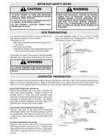
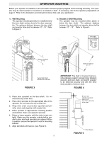
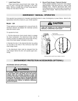
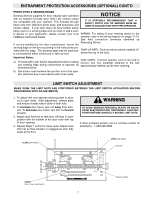
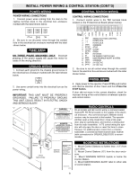
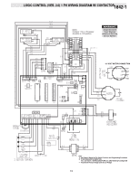
INSTALL POWER WIRING & CONTROL STATION (CONT'D) POWER WIRING POWER WIRING CONNECTIONS 1. Connect power wires coming from the main to the captive terminal block in the electrical box enclosure marked with the label shown below. CONTROL STATION WIRING CONTROL WIRING CONNECTIONS 1. Connect control wires to the TB1 terminal block located on the Printed Circuit Board (shown below). 1 SBC 2 3 4 CMN 5 STOP 6 CLOSE 7 OPEN 8 REV 9 IR 10 MAS 11 CMN 12 24AC+ 13 24AC- 2. Be sure to run all power wires through the conduit hole in the electrical box enclosure marked with the label shown below. ON THREE PHASE MACHINES ONLY: Incorrect phasing of the power supply will cause the motor to rotate in the wrong direction. GROUND WIRING 1. Connect earth ground to the chassis ground screw in the electrical box enclosure marked with the label shown below. 1 SBC SINGLE BUTTON CONTROL 22 INTERLOCK 33 4 CMN 5 STOP INTERLOCK COMMON STOP 6 CLOSE CLOSE 7 OPEN OPEN 8 REV REVERSE 9 IR INFRARED PHOTO EYES 10 MAS MAINTENANCE ALERT SYSTEM 11 CMN COMMON 12 24AC+ 24 VOLT AC 13 24AC- 24 VOLT AC 2. Be sure to run all control wires through the conduit hole in the electrical box enclosure marked with the label shown below. 40-10033B 2. Use same conduit entry into the electrical box as the power wiring. IMPORTANT: THIS UNIT MUST BE PROPERLY GROUNDED. FAILURE TO PROPERLY GROUND THIS UNIT COULD RESULT IN ELECTRIC SHOCK AND SERIOUS INJURY. OR IN THE AREA NEAR THE OPERATOR MUST NOT BE PERFORMED UNTIL DISCONNECTING THE ELECTRICAL POWER AND LOCKING-OUT THE POWER VIA, THE MAIN DISCONNECT SWITCH. UPON COMPLETION OF MAINTENANCE THE AREA MUST BE CLEARED AND SECURED, AT THAT TIME THE UNIT MAY BE RETURNED TO SERVICE. 3. Apply power to the operator. Press OPEN push button and observe direction of door travel and then Press the STOP button. If door did not move in the correct direction, check for improper wiring at the control station or between operator and control station. RADIO CONTROLS On all models with B2 control wiring, a terminal bracket marked R1 R2 R3 is located on the outside of the electrical enclosure. Any commercial type LiftMaster brand receiver may be mounted to this bracket. The operator will then open a fully closed door, close a fully open door, stop an opening door, and reverse a closing door from the radio transmitter. In TS control wiring the operator will only open the door or reset the timer to close. However, for additional door control from a 3 button transmitter, a commercial three-channel radio receiver (with connections for OPEN/CLOSE/STOP) is recommended. Control Station 4 Feet Approximate Optional Controls Maintenance Alert SystemTM If light is Flashing, it is time for routine Door and Opener Maintenance. If light is Steady On, call for immediate service. Service every ________ cycles. MOUNTING INSTRUCTIONS 1. Mount Control Stations no further than (12") from each other. 2. Mount Control Stations (12") from the door enclosure. 3. Mount WARNING NOTICE beside or below the Control Station. 4. Mount MAINTENANCE ALERT label to either side of control station. 9
-
 1
1 -
2
-
3
-
 4
4 -
 5
5 -
 6
6 -
 7
7 -
 8
8 -
 9
9 -
 10
10 -
 11
11 -
 12
12 -
 13
13 -
 14
14 -
15
-
16
-
17
-
18
-
19
-
20
-
21
-
22
-
23
-
24
-
25
-
26
-
27
-
28
 |
 |
