LiftMaster GH GH -Mechanical New style w/ thermal overload change Manual
LiftMaster GH Manual
 |
View all LiftMaster GH manuals
Add to My Manuals
Save this manual to your list of manuals |
LiftMaster GH manual content summary:
- LiftMaster GH | GH -Mechanical New style w/ thermal overload change Manual - Page 1
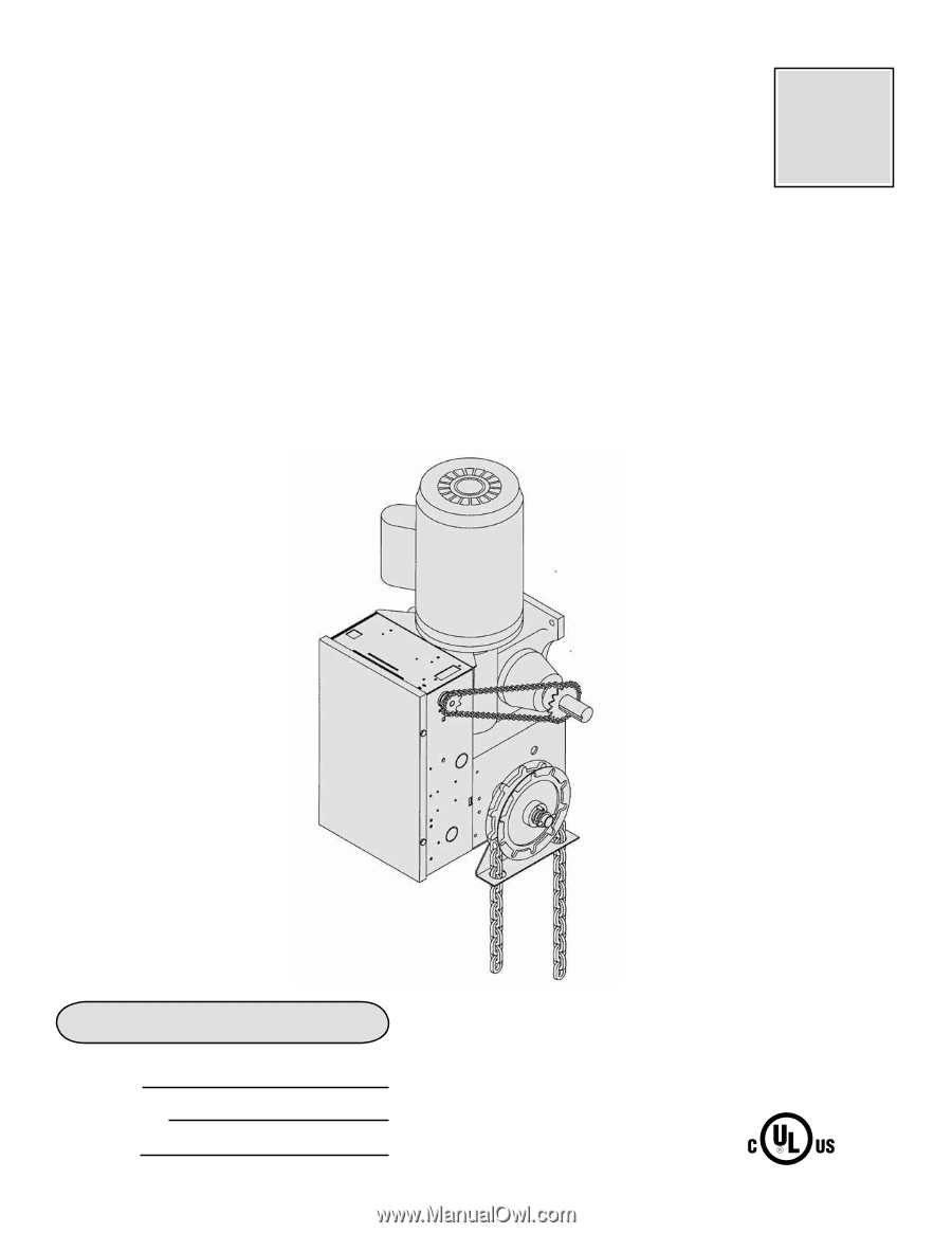
FACTORYSET C2 Wiring See page 6 for other wiring configurations OWNER'S MANUAL GH INDUSTRIAL DUTY COMMERCIAL DOOR OPERATOR 2 YEAR WARRANTY Serial # Box Installation Date Wiring Type NOT FOR RESIDENTIAL USE - LiftMaster GH | GH -Mechanical New style w/ thermal overload change Manual - Page 2
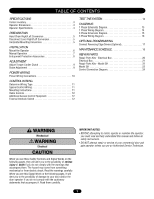
Diagram 15 3 Phase Wiring Diagram 16 OPTIONAL PROGRAMMING Connect Reversing Edge Device (Optional 17 MAINTENANCE SCHEDULE 18 REPAIR PARTS Repair Parts Kits - Electrical Box 20 Electrical Box 21 Repair Parts Kits - Model GH 22 Model GH 23 Control Connection Diagram 24 WARNING Mechanical - LiftMaster GH | GH -Mechanical New style w/ thermal overload change Manual - Page 3
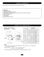
HOIST HAND CHAIN DOOR SPROCKET DOOR/OPERATOR DRIVE CHAIN OPERATOR DIMENSIONS WWEIEGHIGTHS TASNDADNIDMEDNISMIOENNSSIONS HAHNAGNINGGINWGEIWGHETIG: HT: ....8..0..-.18100-1L1B0SL. BS. 14.00" A Y See Note #2 B See Note #1 X C Hand Chain Wheel HP PHASE A 1/2 1 11-1/2 3/4 1 12-1/2 D 1 1 12 - LiftMaster GH | GH -Mechanical New style w/ thermal overload change Manual - Page 4
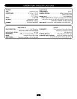
43 RPM DOOR SPEED 4-10" per second depending on door BRAKE Solenoid actuated disc brake HOIST WHEEL Standard mounting on left or right side SAFETY DISCONNECT Floor level chain hoist with electrical interlock for emergency manual door operation. CLUTCH: (Optional Adjustable torque limiter - LiftMaster GH | GH -Mechanical New style w/ thermal overload change Manual - Page 5
move or adjust doors, door springs, cables, pulleys, brackets or their hardware, ALL of which are under EXTREME tension and can cause SERIOUS personal INJURY. AVERTISSEMENT • Disable ALL locks and remove ALL ropes connected to door BEFORE installing and operating door operator to avoid entanglement - LiftMaster GH | GH -Mechanical New style w/ thermal overload change Manual - Page 6
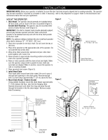
is parallel to door shaft and sprockets are aligned. When in position, secure the operator to wall or mounting bracket. 7. Align sprockets and secure (Figure 3). 8. Install Hand Chain Place hand chain around hand chain wheel. Be sure to pass it through both openings in the chain guide. Remove enough - LiftMaster GH | GH -Mechanical New style w/ thermal overload change Manual - Page 7
controls when the hoist is used. WARNING To prevent possible SERIOUS INJURY from a moving chain, CAUTION ENGAGE interlock BEFORE manually operating your door. To operate the hoist: 1. Pull the disconnect chain (small chain) to engage the interlock to disable the controls. The disconnect chain - LiftMaster GH | GH -Mechanical New style w/ thermal overload change Manual - Page 8
with local codes. TAKE-UP REEL Take-up reel should be installed 12" (30.48 cm) above the top of the door. AVERTISSEMENT COIL CORD Connect operator end of coil cord to junction box (not provided) ATTENTION fastened to the wall approximately halfway up the door opening. WARNING ADJUSTMENT WARNING - LiftMaster GH | GH -Mechanical New style w/ thermal overload change Manual - Page 9
there is very little tension on the clutch spring. 3. Tighten clutch nut gradually until there is just enough tension to permit the operator to move the door smoothly but to allow the clutch to slip if the door is obstructed. When the clutch is properly adjusted, it should generally be possible to - LiftMaster GH | GH -Mechanical New style w/ thermal overload change Manual - Page 10
accordance with local electrical codes. The operator should be on a separate fused line of adequate capacity. • ALL electrical connections MUST be made by a qualified individual. • DO NOT install ANY wiring or attempt to run the operator without consulting the wiring diagram. We recommend that you - LiftMaster GH | GH -Mechanical New style w/ thermal overload change Manual - Page 11
close the door. SPECIAL CONTROL WIRING If your operator was shipped from the factory with non-standard control wiring or with optional accessories that require addition instructions, refer to the wiring diagram(s) indicated in the special control wiring data box. When a replacement wiring diagram is - LiftMaster GH | GH -Mechanical New style w/ thermal overload change Manual - Page 12
know how to use the manual disconnect operation of the door operating system. WARNING DO NOT place hands or tools in or near the operator when the CAUTION power is on or when testing control or safety devices. ALWAYS disconnect power BEFORE servicing or adjusting the operator. ADVERTENCIA PRECAUCI - LiftMaster GH | GH -Mechanical New style w/ thermal overload change Manual - Page 13
MOTOR WIRING 1 - BLUE 2 - WHITE 3 - ORANGE 4 - YELLOW 5 - BLACK 8 - RED O/L- BROWN 13 BL-BK 8 5 OL O/L SEE NOTE 4 42 BL-BK 115V. CONNECTION 1 BL-BK 8 523 4 OL O/L SEE NOTE 4 BL-BK 230V. CONNECTION 230V. BRAKE SOLENOID ( WHEN REQUIRED ) 1 2 3 4 5 7 10 L1 L2 L3 GROUND OPEN CLOSE - LiftMaster GH | GH -Mechanical New style w/ thermal overload change Manual - Page 14
MODELS 2 1 CL (WH) 6 5 MOTOR OVERLOAD (BK) SEE NOTE 4 (BK) (BR) EXTERNAL 4 INTERLOCK HAND CHAIN INTL'K SWITCH (WHEN PRESENT) 5 (BRN) NC C (YEL) (BRN) PRI. T1 (SEE NOTE 3) 24VAC SEC. (YEL) 14 OP 13 1 (OR) IR (Y) C NO (OR) OPEN OP (OR) LIMIT SWITCH (OR) A1 A2 NC C WIRE - LiftMaster GH | GH -Mechanical New style w/ thermal overload change Manual - Page 15
95 OVERLOAD (SEE NOTE 3) 12 3 OPEN CLOSE STOP 4 5 7 10 L1 L2 L3 GROUND EXT. INTLK. TO OPEN AND CLOSE SAFETY EDGE L1 L2 L3 3 PHASE POWER IN (SEE NOTE 2) * - Shipped from Factory CLOSE CONTROL WIRING OPTIONS * C2 WIRING: Constant Presssure to Close RED WIRE ON TERMINAL #2 (Shipped from Factory - LiftMaster GH | GH -Mechanical New style w/ thermal overload change Manual - Page 16
NOTE 3) (BK) 2 (PUR) (YEL) (BK) TO MOTOR HAND CHAIN INTL'K SWITCH (WHEN PRESENT) 5 (BRN) NC C (YEL) (BRN) PRI. T1 (SEE NOTE 2) 24VAC SEC. (YEL) 14 OP 1 13 (OR) (OR) OPEN OP (OR) LIMIT SWITCH (OR) A1 A2 NC C WIRE NUT AUX. CLOSE 10 (GY) LIMIT SWITCH NC C (GY) (RED) R1 - LiftMaster GH | GH -Mechanical New style w/ thermal overload change Manual - Page 17
PROGRAMMING CONNECT REVERSING EDGE DEVICE (OPTIONAL) The operator has been pre-wired to accept connection of a reversing edge device. Connect the normally open the door. NOTICE: This equipment has been tested and found to comply with the limits for a Class A digital device, pursuant to Part 15 - LiftMaster GH | GH -Mechanical New style w/ thermal overload change Manual - Page 18
). • Do not lubricate motor. Motor bearings are rated for continuous operation. • Do not lubricate clutch or V-belt. Repeat ALL procedures. z Inspect and service whenever a malfunction is observed or suspected. AVERTISSEMENT HOW TO ORDER REPAIR PARTS OUR LARGE SERVICE ORGANIZATION SPANS AMERICA - LiftMaster GH | GH -Mechanical New style w/ thermal overload change Manual - Page 19
This page intentionally left blank. 19 - LiftMaster GH | GH -Mechanical New style w/ thermal overload change Manual - Page 20
KITS - ELECTRICAL BOX ITEM 1 2 3 4 5 6 7 8 9 10 11 12 INDIVIDUAL PARTS PART# DESCRIPTION 03-8024-K 10-10020M1 10-10115X 21-5115 Contactor Electrical Box (For Models T, J & H) Electrical Box Cover Transformer, 115V Operators 21-5230 Transformer, 230V Operators 21-5460 23-10916 24-24-1 24-115 - LiftMaster GH | GH -Mechanical New style w/ thermal overload change Manual - Page 21
ELECTRICAL BOX S6 S5 S2 S7 S1 S8 S4 S9 S3 L3 L1 6 7 1 10 L8 L6 L2 3 11 2 4 21 L7 9 12 L2 L5 L4 8 5 - LiftMaster GH | GH -Mechanical New style w/ thermal overload change Manual - Page 22
I.D. 1 08-13333 Bevel Gear, 3/4" I.D. 24 tooth (3HP) 1 10 10-10882 Hand Chain Guide 1 11 12-10883 Nyliner Bearing 1 12 11-11105 Hand Chain Shaft 1 13 12-10029 Bearing, 3/4" I.D. 2 14 18-11008 Compression Spring 1 15 75-10884 Chain Wheel Assembly 1 16 74-30731 Switch Assembly - LiftMaster GH | GH -Mechanical New style w/ thermal overload change Manual - Page 23
MODEL GH K5 3 4 K4 5 K2 2 K1 1 7 6 16 13 K3 12 8 9 13 14 23 11 10 15 - LiftMaster GH | GH -Mechanical New style w/ thermal overload change Manual - Page 24
3 10 *OPEN TIMER TO CLOSE R1 R2 R3 EXTERNAL TERMINAL BLOCK Sensing Device RADIO CONTROL 01-30966C ALL CONTROL WIRING TYPES TIMER TO CLOSE w/ WARNING LIGHT ALL CONTROL WIRING TYPES *T1 WIRING - RADIO TO OPEN ONLY EXTERNAL INTERLOCK Warning Light will activate 15 sec. before door closes. 11
-
 1
1 -
 2
2 -
 3
3 -
 4
4 -
 5
5 -
 6
6 -
 7
7 -
8
-
9
-
10
-
11
-
12
-
13
-
14
-
15
-
16
-
17
-
18
-
19
-
20
-
21
-
22
-
23
-
24
 |
 |
O W N E R ’ S
M A N U A L
GH
INDUSTRIAL DUTY COMMERCIAL DOOR OPERATOR
C2 Wiring
F A C T O R Y S E T
See page 6 for
other wiring
configurations
NOT FOR RESIDENTIAL USE
Serial # Box
Installation Date
Wiring Type
2
YEAR
WARRANTY