LiftMaster GH GH -Mechanical New style w/ thermal overload change Manual - Page 5
Warning - door spring adjustment
 |
View all LiftMaster GH manuals
Add to My Manuals
Save this manual to your list of manuals |
Page 5 highlights
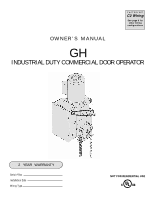
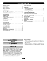
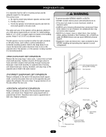
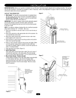
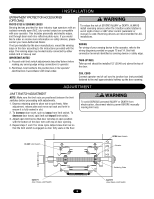
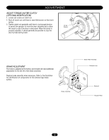
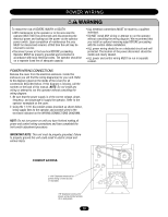
WARNING PREPARATION WARNING CAUTION It is imperative that the wall or mounting surface provide adequate support for the operator. This surface must: a. Be rigid to prevent play between operator and door shaft. b. Provide a level base. c. Permit the operator to be fastened securely and with the drive shaft parallel to the door shaft. The safety and wear of the operator will be adversely affected if any of the above requirements are not met. For metal buildings, fasten 2" x 2" x 3/16" (or larger) angle iron frames to the building purlins. Retain 5-1/2" (13.97 cm) between frames. AVERTISSEMENT The GH operator may be mounted on either the right (standard) or left side of door, and in either a vertical (standard) or horizontal mounting position. Refer to the steps below if you require the hand chain and/or disconnect chain to be on the ATTENTION opposite side of the operator; or if the operator is being mounted in a horizontal position. WARNING To prevent possible SERIOUS INJURY or DEATH: • DO NOT connect electric power until instructed to do so. • If the door lock needs to remain functional, install an interlock switch. • ALWAYS call a trained professional door serviceman if door binds, sticks or is out of balance. An unbalanced door may not reverse when required. • NEVER try to loosen, move or adjust doors, door springs, cables, pulleys, brackets or their hardware, ALL of which are under EXTREME tension and can cause SERIOUS personal INJURY. AVERTISSEMENT • Disable ALL locks and remove ALL ropes connected to door BEFORE installing and operating door operator to avoid entanglement. AVERTISSEMENT HAND CHAIN RIGHT/LEFT CONVERSION Remove the two snap rings (1 piece outer, 1 piece inner) on hand chain shaft assembly. Position roll-pin to fit through cutout in frame and slide complete shaft assembly through housing and bevel gear. Insert shaft assembly on opposite side of housing, and replace bevel gear, bearing, hardware, and snap rings on the opposite side of shaft in the same manner. Shaft Support Bracket with Bearing (Not Provided) Door Sprocket DISCONNECT LEVER RIGHT/LEFT CONVERSION Remove cotterpins on the ends of the disconnect shaft (square shaft), move the disconnect lever arm to the opposite side, and replace the cotterpins. Be sure to keep 12 gauge washers (2) on the side without the lever arm. ADVERTENCIA HORIZONTAL MOUNTING CONVERSION Remove cotterpins on the ends of the disconnect shaft (square PRECAUCIÓN shaft), and remove lever. Replace lever using square hole on opposite end of lever. Reposition sash chain to opposite end of lever also. Replace cotterpins. ADVERTENCIA 5-1/2" (13.97 cm) ADVERTENCIA CAUTION LOCISNAISTTTEEFAMOCOLUFOLRSNPMITNETOBRRDREOSOEOLOCTNORSHTNOUCAATPNSTROEEI8OOSROFLNNAWNTLTSE.LNINOADYIBGETTBOHTYCCVHA3ETEHTBDDCUOOORT-OIONTNRSOERTRNSIEVSOSTLWEET.AIRDTRTIOHINUOSOINNRSCINTTGAIOLELNDASTGIEON Chain Guide Hand Chain Wheel Cutout for Rollpin (typical both sides) Disconnect Lever Cotterpin 5
-
 1
1 -
 2
2 -
 3
3 -
 4
4 -
 5
5 -
 6
6 -
 7
7 -
 8
8 -
 9
9 -
 10
10 -
 11
11 -
12
-
13
-
14
-
15
-
16
-
17
-
18
-
19
-
20
-
21
-
22
-
23
-
24
 |
 |