LiftMaster GH GH -Mechanical New style w/ thermal overload change Manual - Page 10
Power Wiring
 |
View all LiftMaster GH manuals
Add to My Manuals
Save this manual to your list of manuals |
Page 10 highlights
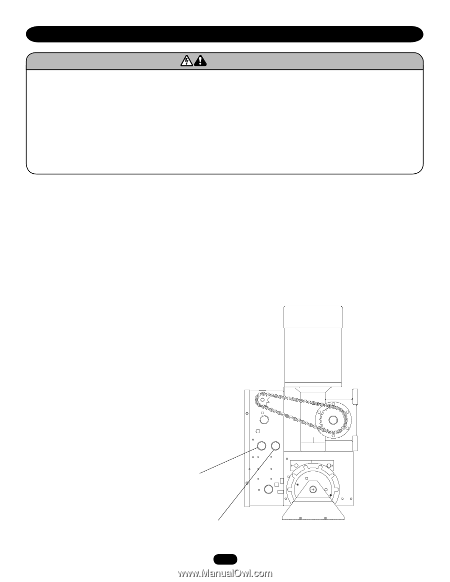
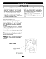
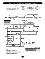
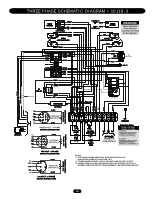
NG P O WWE RARWNI IRNIGN G N WARNING To reduce the risk of SEVERE INJURY or DEATH: • ANY maintenance to the operator or in the area near the operator MUST NOT be performed until disconnecting the electrical power and locking-out the power via the operator power switch. Upon completion of maintenance the area MUST be cleared and secured, at that time the unit may be returned to service. • Disconnect power at the fuse box BEFORE proceeding. Operator MUST be properly grounded and connected in accordance with local electrical codes. The operator should be on a separate fused line of adequate capacity. • ALL electrical connections MUST be made by a qualified individual. • DO NOT install ANY wiring or attempt to run the operator without consulting the wiring diagram. We recommend that you install an optional reversing edge BEFORE proceeding with the control station installation. • ALL power wiring should be on a dedicated circuit and well protected. The location of the power disconnect should be visible and clearly labeled. • ALL power and control wiring MUST be run in separate conduit. EMENT AVERTISSEMENT POWER WIRING CONNECTIONS ON Remove the cover from the electrical enclosure. Inside this AVERTISSEMENT enclosure you will find the wiring diagram(s) for your unit. Refer to the diagram (glued on the inside of the cover) for all connections described below. If this diagram is missing, call the number on the back of this manual. NOTE: Do not install any wiring or attempt to run this operator without consulting the wiring diagram. 1. Be sure that the power supply is of the correct voltage, phase, frequency, and amperage to supply the operator. Refer to the operator nameplate on the cover. 2. Using the 1-1/16" dia conduit access knockout as shown below, bring supply lines to the operator and connect wires to the terminals indicated on the WIRING CONNECTIONS DIAGRAM. NOTE: Do not turn power on until you have finished making all power and control wiring connections and have completed the limit switch adjustment procedure. IMPORTANT NOTE: This unit must be properly grounded. Failure NCIA ADVERTENCIA to properly ground this unit could result in electric shock and serious injury. IÓN ADVERTENCIA CONDUIT ACCESS 1-1/16" Diameter knockout for power wiring conduit access (1 nearside) 7/8" Diameter knockout for power wiring conduit access (2 on end panel) 10
-
 1
1 -
2
-
3
-
4
-
 5
5 -
 6
6 -
 7
7 -
 8
8 -
 9
9 -
 10
10 -
 11
11 -
 12
12 -
 13
13 -
 14
14 -
 15
15 -
16
-
17
-
18
-
19
-
20
-
21
-
22
-
23
-
24
 |
 |