LiftMaster GH GH -Mechanical New style w/ thermal overload change Manual - Page 11
Control Wiring
 |
View all LiftMaster GH manuals
Add to My Manuals
Save this manual to your list of manuals |
Page 11 highlights
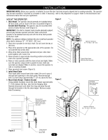
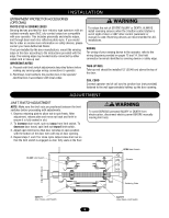
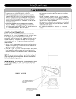
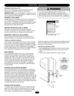
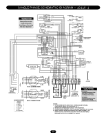
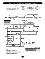
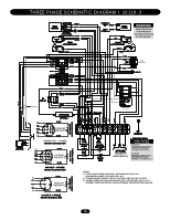
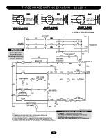
CONTROL WIRING DETERMINE WIRING TYPE Refer to the wiring diagram located on the inside cover the electrical box to determine the type of control wiring. IMPORTANT NOTE: If your wiring diagram is missing, or you are unsure of the wiring type for your operator, contact the customer service department: 1-800-528-2806. STANDARD C2 OR B2 WIRING Standard operators are shipped from the factory with jumper set for C2 wiring, which requires constant pressure on button to close the door. If momentary contact on close direction is desired (B2 wiring) you must include an entrapment protection device. See close control jumper setting below. CONSTANT PRESSURE ON CLOSE (C2 WIRING) Red jumper wire was placed on terminal #2 in electrical enclosure. The operator will require constant pressure on close control in order to keep door moving in the close direction. MOMENTARY CONTACT ON CLOSE (B2 WIRING) Move red jumper wire from terminal #2 to terminal #3. The operator will require only momentary contact to close the door. SPECIAL CONTROL WIRING If your operator was shipped from the factory with non-standard control wiring or with optional accessories that require addition instructions, refer to the wiring diagram(s) indicated in the special control wiring data box. When a replacement wiring diagram is present, wiring diagrams in this manual will not apply. Refer only to the replacement wiring diagram for all connections. RADIO CONTROLS On all models with type B2 control wiring, a terminal bracket marked R1 R2 R3 is located on the outside of the electrical enclosure. All standard radio control receivers (single channel residential type) may be mounted to this bracket. The operator will then open a fully closed door, close a fully open door, and reverse a closing door from the radio transmitter. However, for complete door control from a transmitter, a commercial three-channel radio set (with connections for Open/Close/Stop) is recommended. ADDITIONAL ACCESS CONTROL EQUIPMENT Locate any additional access control equipment as desired (but so that the door will be in clear sight of the person operating the equipment), and connect to the terminal block in the electrical enclosure as shown on the Field Wiring Connections diagram. Any control with a normally (N.O.) isolated output contact may be connected in parallel with the OPEN button. More than one device may be connected in this manner. Use 16 gauge wire or larger for all controls. Do not use the Control Circuit Transformer (24 Vac) in the Operator to power any access control equipment other than a standard residential type radio receiver. WARNING To prevent possible SERIOUS INJURY or DEATH, install CAUTION reversing sensors when the 3-button control station is out of sight of the door or ANY other control (automatic or manual) is used. Reversing devices are recommended for ALL installations. SPECIAL CONTROL WIRING DIAGRAM This Operator has Control Wiring. SUPPLEMENTAL WIRING DIAGRAM(S) REPLACEMENT WIRING DIAGRAM WI Wiring Type Note: Supplemental Wiring Diagrams are to be used in addition to 1742-1. Replacement Wiring Diagram is to be used in place of 1742-1 AVERTISSEMENT WWiirrinignDgiagraDm liaabegl onrainsmide coLverabel on Inside Cover of of electrical box Electrical Box ATTENTION Connections diagram, the control circuit will be disabled when the switch is actuated, thereby preventing electrical operation of the door from the control devices. MOUNTING INSTRUCTIONS 1. Mount WARNING NOTICE beside or below the control station. 2. Mount MAINTENANCE ALERT label to either side of control station. 3. Mount control station(s) within line of sight of door(s). ADVERTENCIA OR IN THE AREA NEAR THE OPERATOR MUST NOT BE PERFORMED UNTIL DISCONNECTING THE ELECTRICAL POWER AND LOCKING-OUT THE POWER VIA, THE MAIN DISCONNECT SWITCH. UPON COMPLETION OF MAINTENANCE THE AREA MUST BE CLEARED PRECAUCIÓNAND SECURED, AT THAT TIME THE UNIT MAY BE RETURNED TO SERVICE. Control Station Optional Controls 4' Approximate EXTERNAL INTERLOCK SWITCH The operator has a terminal connection for an external interlock switch. This switch must be a normally closed (N.C.) two-wire device with a contact rating of at least 3 amps at 24 Vac. When such a switch is connected as shown on the Field Wiring 11
-
 1
1 -
2
-
3
-
4
-
5
-
 6
6 -
 7
7 -
 8
8 -
 9
9 -
 10
10 -
 11
11 -
 12
12 -
 13
13 -
 14
14 -
 15
15 -
 16
16 -
17
-
18
-
19
-
20
-
21
-
22
-
23
-
24
 |
 |