LiftMaster GH GH -Mechanical New style w/ thermal overload change Manual - Page 12
Control Wiring Cont'd, Test The System
 |
View all LiftMaster GH manuals
Add to My Manuals
Save this manual to your list of manuals |
Page 12 highlights
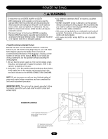
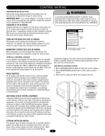
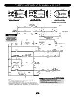
CONTROL WIRING (CONT'D) RADIO CONTROLS On all models with type B2 control wiring, a terminal bracket marked R1 R2 R3 is located on the outside of the electrical enclosure. All standard radio control receivers (single channel residential type) may be mounted to this bracket. The operator will then open a fully closed door, close a fully open door, and reverse a closing door from the radio transmitter. However, for complete door control from a transmitter, a commercial threechannel radio set (with connections for OPEN/CLOSE/STOP) is recommended. WARNING DO NOT use radio controls with your operator unless you CAUTION have installed some type of entrapment protection device. The use of radio controls presents potential hazards due to the user's ability to open or close the door when out of sight of the door. In addition, if a single channel control is used, the user will not be able to stop the door from the remote control. ADDITIONAL ACCESS CONTROL EQUIPMENT Locate any additional access control equipment as desired (but so that the door will be in clear sight of the person operating the equipment), and connect to the terminal block in the electrical enclosure as shown on the FIELD WIRING CONNECTIONS diagram. Any control with a normally (N.O.) isolated output contact may be connected in parallel with the OPEN button. More than one device may be connected in this manner. Use 16 gauge wire or larger for all controls. NOTE: Do not use the control circuit transformer (24Vac) in the operator to power any access control equipment other than a standard residential type radio receiver. EXTERNAL INTERLOCK SWITCH The operator has a terminal connection for an external interlock switch. This switch must be a normally closed (N.C.) two-wire device with a contact rating of at least 3 amps at 24 Vac. When such a switch is connected as shown on the FIELD WIRING AVERTISSEMENT CONNECTIONS diagram, the control circuit will be disabled when the switch is actuated, thereby preventing electrical operation of the door from the control devices. ATTENTION TEST THE SYSTEM Turn on power. Test all controls and safety devices to make sure they are working properly. It will be necessary to refer back to page 6 for fine adjustment of the limit switches. IMPORTANT NOTES: • Do not leave operator power on unless all safety and entrapment protection devices have been tested and are working properly. • Be sure you have read and understand all Safety Instructions included in this manual. • Be sure the owner or person(s) responsible for operation of the door have read and understand the Safety Instructions, know how to electrically operate the door in a safe manner, and know how to use the manual disconnect operation of the door operating system. WARNING DO NOT place hands or tools in or near the operator when the CAUTION power is on or when testing control or safety devices. ALWAYS disconnect power BEFORE servicing or adjusting the operator. ADVERTENCIA PRECAUCIÓN AVERTISSEMENT ATTENTION 12
-
 1
1 -
2
-
3
-
4
-
5
-
6
-
 7
7 -
 8
8 -
 9
9 -
 10
10 -
 11
11 -
 12
12 -
 13
13 -
 14
14 -
 15
15 -
 16
16 -
 17
17 -
18
-
19
-
20
-
21
-
22
-
23
-
24
 |
 |