LiftMaster HCTDCU HCTDCU Installation Manual
LiftMaster HCTDCU Manual
 |
View all LiftMaster HCTDCU manuals
Add to My Manuals
Save this manual to your list of manuals |
LiftMaster HCTDCU manual content summary:
- LiftMaster HCTDCU | HCTDCU Installation Manual - Page 1
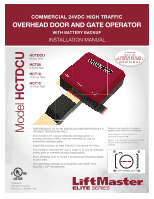
PHOTOREGISTERSM COMMERCIAL 24VDC HIGH TRAFFIC OVERHEAD DOOR AND GATE OPERATOR WITH BATTERY BACKUP INSTALLATION MANUAL HCTDCU Motor Unit HCT08 8 Foot Rail HCT10 10 Foot Rail HCT12 12 Foot Rail • THIS PRODUCT IS TO BE INSTALLED AND SERVICED BY A TRAINED TECHNICIAN ONLY. • This model is for use on - LiftMaster HCTDCU | HCTDCU Installation Manual - Page 2
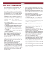
, you must read and fully understand this manual and follow all safety instructions. • Operator intended to be installed on a properly balanced gate/door only. Make sure gate/door is properly balanced before installing. • DO NOT attempt repair or service of your operator unless you are an Authorized - LiftMaster HCTDCU | HCTDCU Installation Manual - Page 3
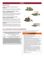
INJURY or DEATH: • READ AND FOLLOW ALL INSTRUCTIONS. • NEVER let children operate or play with gate/door controls. Keep OPERATING AND BALANCED. Read the gate/door manufacturer's owner's manual. An improperly operating or balanced gate/door could cause severe INJURY or DEATH. Have a qualified service - LiftMaster HCTDCU | HCTDCU Installation Manual - Page 4
Instructional and Precautionary Signage 4. Install the gate operator only when: a. The operator operator. 8. Controls intended for user activation must be located at least 6 feet (1.8 m) away from any moving part gate operator utilizing a non-contact sensor: a. Reference owner's manual regarding - LiftMaster HCTDCU | HCTDCU Installation Manual - Page 5
manually operated gate is retrofitted with a powered gate operator. 1.6 A gate latch shall not be installed on an automatically operated the gate will enter a receiver guide. Class IV vehicular vertical pivot support the weight of the gate at any position of the gate. Class IV vehicular overhead - LiftMaster HCTDCU | HCTDCU Installation Manual - Page 6
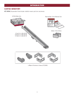
NOT SHOWN: Documentation Packet (includes installation manual, quick start, and antenna) HCTDCU Motor Unit Warning Signs (2) and Warranty Card 8 Foot (2.4 m) Rail HCT08 10 Foot (3.1 m) Rail HCT10 12 Foot (3.7 m) Rail HCT12 Battery 12 Vdc 7AH (2) LiftMaster Photoelectric Sensors (CPSUN4G) 6 - LiftMaster HCTDCU | HCTDCU Installation Manual - Page 7
Weights) Maximum Gate/Door Weight Maximum Gate/Door Width (sectional and one-piece) Travel Speed Maximum Daily Cycle Rate Maximum Duty Cycle Operating Temperature Expansion Board Inherent Entrapment Protection (Type A) External Entrapment Protection (Type B1 and/or Type B2) Class II, III, and IV - LiftMaster HCTDCU | HCTDCU Installation Manual - Page 8
risk of nuisance tripping, such as when a vehicle trips the sensor while the gate/door is still moving. Brackets (not provided) Flush Mount Operator Edge Sensor Make sure the gate opens and closes smoothly. Gate should stay in the open position when springs are properly balanced. Warning Sign - LiftMaster HCTDCU | HCTDCU Installation Manual - Page 9
door or ANY moving part of the gate/door 11. This operator is intended for INSTRUCTIONS. • ALWAYS wear protective gloves and eye protection when changing the battery or working around the battery compartment. • NEVER wear watches, rings or loose clothing while installing or servicing operator - LiftMaster HCTDCU | HCTDCU Installation Manual - Page 10
the screws and open the cover of the operator. 2. Remove the chain guard from the chassis. 3. Lay the rail on the floor. Align the key holes on the end of the rail with the - LiftMaster HCTDCU | HCTDCU Installation Manual - Page 11
gear reducer and replace it with the vented plug (provided in bag with manual). 3. Tighten the vented plug with a socket or Allen wrench. 4. Re-insert the dome plug. Dome Plug Vented Plug STEP 3 DETERMINE LOCATION FOR OPERATOR 1. With the gate/door closed, mark the center. 2. Open the gate/door - LiftMaster HCTDCU | HCTDCU Installation Manual - Page 12
and align with center mark on ceiling. Have someone hold the operator in place or use a post as a temporary support. Bolt the operator to the ceiling. (A support post is not part of the operator. Use only for installation.) Concrete Anchor 1/2" x 3 1/2" Brackets (not provided) 3. Bolt or weld - LiftMaster HCTDCU | HCTDCU Installation Manual - Page 13
A monitored device sends a pulsed signal to the operator so the operator is aware of the device. If the operator does not receive the signal from the device it will to test entrapment protection devices monthly. Use only LiftMaster approved entrapment protection devices (refer to the accessory - LiftMaster HCTDCU | HCTDCU Installation Manual - Page 14
protection devices depending on the specific device and how the device will function. Refer to the specific entrapment protection device manual for more information. These entrapment protection device inputs are for monitored devices, which include pulsed photoelectric sensors, resistive edge - LiftMaster HCTDCU | HCTDCU Installation Manual - Page 15
time the unit may be returned to service. • Disconnect power at the fuse box BEFORE proceeding. Operator MUST be properly grounded and connected in STEP 6 POWER WIRING NOTE: The operator can also be powered by solar panels, refer to the dealer extranet on LiftMaster.com for more information. Proper - LiftMaster HCTDCU | HCTDCU Installation Manual - Page 16
J15 plug into the board. 8. Attach the provided antenna in the orientation shown. ONLY use the provided antenna. 9. Turn ON AC power to the operator. 10. Turn ON the AC power switch on the operator. Red Wire (+) Black Wire (-) Black jumper provided with batteries Provided Antenna J15 Plug 16 - LiftMaster HCTDCU | HCTDCU Installation Manual - Page 17
LIMIT SETTING MODE Limits are set. 1 2 INITIAL LIMITS AND FORCE ADJUSTMENT The gate/door MUST be attached to the operator before setting the limits and force. 1. Press and release the SET OPEN and SET CLOSE buttons simultaneously to enter limit setting mode. 2. Press and hold one of the MOVE GATE - LiftMaster HCTDCU | HCTDCU Installation Manual - Page 18
gate/door directions. 1. Open and close the gate/door with the TEST BUTTONS. 2. If the gate/door stops or reverses before reaching the fully open or . After any adjustments are made, test the operator: 1. Open and close the gate/door with the TEST BUTTONS, ensuring that the gate/door is stopping at - LiftMaster HCTDCU | HCTDCU Installation Manual - Page 19
OPERATOR OVERVIEW AC POWER SWITCH EMI BOARD RESET BUTTON CONTROL BOARD EXPANSION BOARD TROLLEY RAIL RELEASE RING 19 - LiftMaster HCTDCU | HCTDCU Installation Manual - Page 20
button as an open, close, and stop. Program each remote control button as an open, close, and stop. PROGRAM USING OPERATOR'S LEARN BUTTON 1. Press and release the LEARN button (operator B digital device, pursuant to part 15 of the FCC rules. in accordance with the instructions, may cause harmful - LiftMaster HCTDCU | HCTDCU Installation Manual - Page 21
connection and a Wi-Fi® router to use the LiftMaster Internet Gateway. To program the operator to the LiftMaster Internet Gateway: PROGRAM MyQ® USING THE LEARN BUTTON ON THE OPERATOR'S CONTROL BOARD 1. Connect the ethernet cable to the LiftMaster Internet Gateway and the router. 2. Connect power to - LiftMaster HCTDCU | HCTDCU Installation Manual - Page 22
is in the desired close position, press and release the STOP button on the remote control. 4. Press and release the CLOSE button on the remote control again to set the close limit. When the close limit is set properly the operator will automatically exit limit setting mode. Set the Open Limit Only - LiftMaster HCTDCU | HCTDCU Installation Manual - Page 23
Attach alert signal (audible or visual alert system) to indicate if gate/door is manually tampered with by being pushed off of close limit. Use during servicing only to determine operator cycles. Connect emergency access system (Knox box switch, SOS system, etc.). COMMERCIAL INDUSTRIAL Normally - LiftMaster HCTDCU | HCTDCU Installation Manual - Page 24
the force. See Force Adjustment section. 9 TEST BUTTONS: The TEST BUTTONS will operate the gate/door (OPEN, STOP and CLOSE). 10 STATUS LEDs: The STATUS LEDs indicate the status of the operator. See Status LED Chart in the Troubleshooting section. 11 DIAGNOSTIC CODE DISPLAY: The diagnostic code - LiftMaster HCTDCU | HCTDCU Installation Manual - Page 25
the alarm and reset the operator. After the operator is reset, normal functions will resume. ADJUSTABLE OPEN SPEED The HCTDCU provides a high speed open the gate/door is in the open position, activation of the remote control button will close the gate/door. If the remote control is activated while - LiftMaster HCTDCU | HCTDCU Installation Manual - Page 26
MANUAL DISCONNECT OPERATION To reduce the risk of SERIOUS INJURY or DEATH from a falling gate/door: • If possible, use manual release to disengage trolley ONLY when gate/door is CLOSED. Weak or broken springs or unbalanced gate/door could result in an open gate/door - LiftMaster HCTDCU | HCTDCU Installation Manual - Page 27
in the open position. To restart the Timer-to-Close either press the reset button or activate the gate/door with a programmed remote control. • Press the reset button to shut off the alarm and reset the operator. WIRING • STOP and COM: Stops a moving gate/door. Hard stop (maintained switch overrides - LiftMaster HCTDCU | HCTDCU Installation Manual - Page 28
ACCESSORY WIRING MISCELLANEOUS WIRING THREE BUTTON CONTROL STATION (4 Terminals) • OPEN and COM: Opens UNSWITCHED: 24 Vdc voltage out to power accessories, always ON. (Main control board) Three Button Control Station Open Close Stop N.C. Com Fire Dept Com Fire Department (Main control board) - LiftMaster HCTDCU | HCTDCU Installation Manual - Page 29
31 for red/green light functionality. The RGL24LY will run when the operator is on battery backup power. WIRING: Expansion board 1. Connect the COM The ACC PWR OVLD LED on the main board will light if there is a problem with the radio. SIGNAL: 1. Locate the signal wires from the receiver. There - LiftMaster HCTDCU | HCTDCU Installation Manual - Page 30
-to-Close). BATT: With loss of AC power, gate/door will remain in present position and operator is powered from batteries. 3 EXIT LOOP FAIL Switch: When set to OPEN, if the EXIT plug-in loop detector (Model LOOPDETLM) detects a fault, then the gate/door will open and remain open until fault is - LiftMaster HCTDCU | HCTDCU Installation Manual - Page 31
is manually tampered with by being pushed Energizes if gate/door is manually tampered determine the actual cycles that the gate/door operator has run (in thousands), set all three is between 1,000 and 9,999,000 cycles. After servicing, set Aux Relay switches back to their appropriate positions. - LiftMaster HCTDCU | HCTDCU Installation Manual - Page 32
Close Direction Photoelectric Sensors, Infra-red detector wired or Edge to inputs Sensor, Close: reverses fully, Open: stops gate/door B Single Button Control, SBC (2 terminals) Gate/door command sequence - Open, Stop, Close, Stop, ... Soft Open ,Soft Close, Soft Stop (maintained switch does not - LiftMaster HCTDCU | HCTDCU Installation Manual - Page 33
ONLY LiftMaster part 29-NP712 for replacement batteries. • SAVE THESE INSTRUCTIONS. • ALWAYS wear protective gloves and eye protection when changing the battery or working around the battery compartment. MAINTENANCE CHART Disconnect all power (AC, solar, battery) to the operator before servicing - LiftMaster HCTDCU | HCTDCU Installation Manual - Page 34
TROUBLESHOOTING To protect against fire and electrocution: • DISCONNECT power (AC or solar and battery) BEFORE installing or servicing operator and hold the STOP button for six seconds. The display will show "Er" then "CL" alternately for six seconds. 2. Release the STOP button. The code history has - LiftMaster HCTDCU | HCTDCU Installation Manual - Page 35
TROUBLESHOOTING DIAGNOSTIC CODES Some codes are saved in the code history and some are not. If a code is not saved it will briefly appear on the display as it occurs, then disappear. LiftMaster against a non-resilient hard stop (re-adjust limit). Operator may be at end of travel (re-adjust mounting - LiftMaster HCTDCU | HCTDCU Installation Manual - Page 36
TROUBLESHOOTING DIAGNOSTIC CODES Some codes are saved in the code history and some are not. If a code is not saved it will briefly appear on the display as it occurs, then disappear. LiftMaster the close direction must be installed to allow operation. CLOSE EYE/INTERRUPT held more than 3 minutes - LiftMaster HCTDCU | HCTDCU Installation Manual - Page 37
TROUBLESHOOTING CONTROL BOARD LEDS INPUT OFF POWER ON STATUS LEDS OFF state per second) The gate/door is stopped The gate/door is opening or closing Operator is in E1 (single entrapment) FASTEST BLINK (8 The operator is in E2 (double blinks per second) entrapment) BATT LOW OFF No battery - LiftMaster HCTDCU | HCTDCU Installation Manual - Page 38
limit and the CLOSE limit. a) Use manual disconnect, manually move gate/door, and ensure gate/door moves learn wireless control/transmitter to control board. Replace wireless control as needed. b) Check Stop button is not "stuck on". c) Check Reset button. d) Check if similar wired control operates - LiftMaster HCTDCU | HCTDCU Installation Manual - Page 39
TROUBLESHOOTING TROUBLESHOOTING CHART continued... SYMPTOM Exit loop activation does not cause gate/ a) Check for cause of entrapment (obstruction) detection and correct. Press the reset button to shut off alarm and reset the operator. a) Check if AC power is available. If no AC power, then running - LiftMaster HCTDCU | HCTDCU Installation Manual - Page 40
TROUBLESHOOTING TROUBLESHOOTING CHART continued Relay wiring incorrect c) Defective Expansion board SOLUTIONS a) Learn the limits. a) Move accessory to accessory power . a) Check that Quick Close setting is ON. b) Check operation of Interrupt Loop detector. c) Replace defective Expansion board. a) - LiftMaster HCTDCU | HCTDCU Installation Manual - Page 41
power (AC or solar and battery) BEFORE installing or servicing operator. For continued protection against fire: • Replace ONLY with Orange Black Red Product ID Red Red Black Piezo Alarm White White Reset Button APS Encoder 1/2 HP 24 Vdc Motor GROUND HOT NEUTRAL Green White Black - LiftMaster HCTDCU | HCTDCU Installation Manual - Page 42
REPAIR PARTS Operator Cover K10-37598 Chassis and Cover K75-38058 Main Control Board K1D8389-1CC Battery Access Door K10-37595 Expansion Board K1D8387-1CC Two 7AH batteries - LiftMaster HCTDCU | HCTDCU Installation Manual - Page 43
a full list of optical edges see LiftMaster.com LIFTMASTER MONITORED RETROREFLECTIVE PHOTOELECTRIC SENSOR Model LMRRU and CPS-RPEN4GM PVC CHANNEL 1-3/4" x 1-3/4" - Model OES-4504 2" x 2" - Model OES-5104 LIFTMASTER COMMERCIAL PROTECTOR SYSTEM® Models CPS-UN4 and CPSUN4G PLASTIC CHANNEL 8 foot - LiftMaster HCTDCU | HCTDCU Installation Manual - Page 44
after 1993. Contact your authorized LiftMaster dealer for additional details and options. 3-BUTTON REMOTE CONTROL The 3-button remote control can be programmed to control the operator. Includes visor clip. Model 893MAX 3-BUTTON MINI-REMOTE CONTROL The 3-button remote control can be programmed to - LiftMaster HCTDCU | HCTDCU Installation Manual - Page 45
this product. Then send this product, pre-paid and insured, to our service center for warranty repair. You will be advised of shipping instructions when you call. Please include a brief description of the problem and a dated proof-of-purchase receipt with any product returned for warranty repair - LiftMaster HCTDCU | HCTDCU Installation Manual - Page 46
01-37718B 845 Larch Avenue Elmhurst, Illinois 60126-1196 LiftMaster.com Wi-Fi® is a registered trademark of Wi-Fi Alliance © 2016, LiftMaster - All Rights Reserved - LiftMaster HCTDCU | HCTDCU Installation Manual - Page 47
m (10 pi) HCT12 Rail de 3,7 m (12 pi) Modèle HCTDCU PHOTOREGISTERSM • CE PRODUIT DOIT ÊTRE EXCLUSIVEMENT INSTALLÉ ET ENTRETENU PAR UN TECHNICIEN ou de porte commerciale de classes II, III et IV. • Aller sur LiftMaster.com pour localiser le détaillant-installateur le plus proche. • Cet actionneur - LiftMaster HCTDCU | HCTDCU Installation Manual - Page 48
19 PROGRAMMATION 20 TÉLÉCOMMANDES (NON FOURNIES 20 PASSERELLE INTERNET LIFTMASTER (NON FOURNIES 21 EFFACEMENT DE TOUS LES CODES 21 , vous devez lire et comprendre intégralement ce manuel et appliquer toutes les instructions de sécurité. • L'ouvre-porte est conçu pour être installé uniquement - LiftMaster HCTDCU | HCTDCU Installation Manual - Page 49
de BLESSURES GRAVES, voire MORTELLES : • LIRE ET OBSERVER TOUTES LES INSTRUCTIONS. • Ne JAMAIS laisser un enfant faire fonctionner ou jouer avec les causer des BLESSURES GRAVES, voire AVERTISS MORTELLES. Demander à un technicien de service compétent de réparer la quincaillerie de la porte ou de la - LiftMaster HCTDCU | HCTDCU Installation Manual - Page 50
: • Arêtes de barrière • Capteurs photoélectriques • Poteaux verticaux • Gardes pour rouleaux exposés • Mailles d'écrans • Panneaux indicateurs pour instructions et avertissements 9. La fonction d'arrêt et/ou réinitialisation (si fournie séparément) doit être située dans la ligne visuelle de la - LiftMaster HCTDCU | HCTDCU Installation Manual - Page 51
une stabilité latérale suffisante pour que la barrière entre dans un guide récepteur. Les barrières véhiculaires à pivotement vertical de classe IV doivent de rails et de quincaillerie connexe doivent être conçus pour pouvoir supporter le poids de la barrière dans n'importe quelle position de sa - LiftMaster HCTDCU | HCTDCU Installation Manual - Page 52
INTRODUCTION CONTENU DE L'EMBALLAGE NON ILLUSTRÉS : Documentation (comprend le manuel d'installation, de démarrage rapide et l'antenne) HCTDCU Moteur Panneaux d'avertissement (2) et Carte de garantie Rail de 2,4 m (8 pi) HCT08 Rail de 3,1 m (10 pi) HCT10 Rail de 3,7 m (12 pi) HCT12 Pile 12 Vcc 7 - LiftMaster HCTDCU | HCTDCU Installation Manual - Page 53
barrière/porte Largeur maximale de la barrière/porte (articulée et rigide) Vitesse de course Capacité de cycles quotidienne maximale Cycle de service maximal Température de fonctionnement Tableau d'extension Protection inhérente contre le piégeage (Type A) Protection externe contre le piégeage (Type - LiftMaster HCTDCU | HCTDCU Installation Manual - Page 54
le risque de déclenchement adverse, par exemple, un véhicule qui déclenche le capteur alors que la barrière/porte est toujours en mouvement. Supports (non fournis) Montage affleurant Actionneur Bordure de détection S'assurer que la barrière s'ouvre et se ferme aisément. La barrière doit rester - LiftMaster HCTDCU | HCTDCU Installation Manual - Page 55
de commande. Fixer de façon permanente chaque panneau d'avertissement d'une manière appropriée à l'aide des trous de fixation. 13. CONSERVER CES INSTRUCTIONS. ATTENTION • PORTEZ TOUJOURS des gants de protection et des lunettes de sécurité lorsque vous changez la pile ou travaillez aux alentours du - LiftMaster HCTDCU | HCTDCU Installation Manual - Page 56
INSTALLATION ÉTAPE 1 RACCORDER LE RAIL À L'ACTIONNEUR 1. Enlever les vis et ouvrir le couvercle de l'actionneur. 2. Enlever le carter de chaîne du châssis. 3. Déposer le rail sur le sol. Aligner les orifices à l'extrémité du rail sur les vis d'assemblage du châssis. 4. Fixer le rail au châssis avec - LiftMaster HCTDCU | HCTDCU Installation Manual - Page 57
INSTALLATION ÉTAPE 2 INSTALLER LE BOUCHON DE MISE À L'AIR LIBRE 1. Enlever le bouchon bombé du châssis de l'actionneur. 2. Enlever le bouchon plein dans le démultiplicateur à engrenage et le remplacer par le bouchon de mise à l'air libre (fourni dans le sac avec le manuel). 3. Serrer le bouchon de - LiftMaster HCTDCU | HCTDCU Installation Manual - Page 58
moteur sur le matériel d'emballage pour protéger le carter. S'assurer que le support du linteau se trouve au centre de l'ouverture. Boulonner ou souder le support du linteau à la paroi murale. Support de linteau Support de linteau 2. Soulever l'actionneur et l'aligner sur le repère du centre au - LiftMaster HCTDCU | HCTDCU Installation Manual - Page 59
tous les mois les dispositifs de protection contre le piégeage. Utiliser uniquement les dispositifs de protection contre le piégeage approuvés par LiftMaster (consulter la page des accessoires). CAPTEURS SANS CONTACT Si le faisceau du capteur photoélectrique est bloqué pendant que la barrière/porte - LiftMaster HCTDCU | HCTDCU Installation Manual - Page 60
INSTALLATION STEP 5 (suite) INSTALLER LE DISPOSITIF DE PROTECTION CONTRE LE PIÉGEAGE Il existe trois options de câblage pour les dispositifs de protection contre le piégeage selon le dispositif particulier utilisé et la façon dont il fonctionnera. Consulter le manuel particulier au dispositif de - LiftMaster HCTDCU | HCTDCU Installation Manual - Page 61
sécurisée, c'est seulement à ce moment que l'unité peut être remise en service. • Déconnectez l'alimentation au niveau de la boîte à fusibles AVANT de par des panneaux solaires; consulter l'extranet du détaillant sur LiftMaster.com pour plus d'information. CALIBRAGE AMÉRICAIN NORMALISÉ DES - LiftMaster HCTDCU | HCTDCU Installation Manual - Page 62
CÂBLAGE ÉTAPE 7 CONNECTER LES BATTERIES ET FIXER L'ANTENNE Les batteries sont chargées dans le circuit par le transformateur intégré. Les batteries servent à l'alimentation de secours. 1. Débrancher la fiche J15 étiquetée BATT sur le tableau de commande en pinçant la fiche et en en l'extrayant du - LiftMaster HCTDCU | HCTDCU Installation Manual - Page 63
AJUSTEMENT RÉGLAGES DE COURSE ET DE FORCAETTENTION AVERTISSEMENT Pour réduire le risque de BLESSURES GRAVES, voire MORTELLES : AVERTISSEMENT • Sans un système d'inversion de sécurité correctement installé, des personnes (plus particulièrement les jeunes enfants) pourraient être • Ne JAMAIS - LiftMaster HCTDCU | HCTDCU Installation Manual - Page 64
directions d'ouverture et de fermeture de la barrière/porte. 1. Ouvrir et fermer la barrière/porte à l'aide des boutons de mise à l'essai (TEST BUTTONS). 2. Si la barrière/porte s'arrête ou inverse sa course avant d'atteindre la position d'ouverture ou de fermeture complète, augmenter la résistance - LiftMaster HCTDCU | HCTDCU Installation Manual - Page 65
PRÉSENTATION DE L'ACTIONNEUR INTERRUPTEUR D'ALIMENTATION CA CARTE DE FILTRE EMI INTERRUPTEUR DE RÉINITIALISATION CARTE DE CONTRÔLE TABLEAU D'EXTENSION CHARIOT RAIL BAGUE DE DÉVERROUILLAGE 19 - LiftMaster HCTDCU | HCTDCU Installation Manual - Page 66
vous désirez programmer. 1. Enfoncer et relâcher le bouton d'apprentissage (LEARN) (l'actionneur émettra un bip et la DEL verte XMITTER s'allumera). et, s'il n'est pas installé et utilisé conformément aux instructions, causer des interférences nuisibles aux communications radio. Cependant, il n' - LiftMaster HCTDCU | HCTDCU Installation Manual - Page 67
L'actionneur de la barrière/porte peut être commandé par l'application de la passerelle Internet LiftMaster. EFFACEMENT DE TOUS LES CODES 1. Appuyer et relâcher le bouton d'apprentissage de radio (LEARN RADIO) (l'actionneur émettra un bip et la DEL verte XMITTER s'allumera). 2 Enfoncer et tenir de - LiftMaster HCTDCU | HCTDCU Installation Manual - Page 68
PROGRAMMATION RÉGLAGE DE LIMITE DE COURSE AVEC UNE TÉLÉCOMMANDE Réglage de limite de course avec une télécommande Le réglage des limites avec une télécommande nécessite d'abord une télécommande à 3 boutons qui a été programmée pour Ouvrir, Fermer et Arrêter. Se reporter à la section Programmation. - LiftMaster HCTDCU | HCTDCU Installation Manual - Page 69
Relai aux - Délai prémouvement Sortie Relai aux - Alimentation Sortie Relai aux - Effraction Rétroaction de quantité de cycles Entrée ouvert service incendie 2) Connecte le témoin « Barrière ouverte » (p.ex. lampe). 2) Connecte le témoin « Barrière ouverte » (p.ex. lampe). Habituellement non - LiftMaster HCTDCU | HCTDCU Installation Manual - Page 70
25. 6 Bouton APPRENDRE (LEARN) : Le bouton APPRENDRE (LEARN) permet de programmer les télécommandes Les boutons de mise à l'essai (TEST BUTTONS) font fonctionner la barrière/porte (ouverture, de « 24 », indiquant que l'actionneur est de type HCTDCU. La version du matériel sera montrée après le - LiftMaster HCTDCU | HCTDCU Installation Manual - Page 71
êter l'alarme et réinitialiser l'actionneur. Lorsque l'actionneur est réinitialisé, les fonctions normales reprendront. VITESSE D'OUVERTURE RÉGLABLE Le modèle HCTDCU fournit une option de grande vitesse d'ouverture pour aider à assurer une circulation plus fluide dans les zones de trafic intense - LiftMaster HCTDCU | HCTDCU Installation Manual - Page 72
DÉBRANCHEMENT MANUEL FONCTIONNEMENT ATTENTION AVERTISSEMENT Pour réduire le risque de BLESSURES GRAVES ou MORTELLES causées par la chute d'une barrière/porte : AVERTISSEMENT • Si possible, utiliser la poignée de déclenchement d'urgence pour désengager le chariot UNIQUEMENT lorsque la barrière/ - LiftMaster HCTDCU | HCTDCU Installation Manual - Page 73
CÂBLAGE DES ACCESSOIRES DISPOSITIFS DE COMMANDE EXTÉRIEURS SORTIE (2 bornes) Cette entrée est une commande d'ouverture provisoire (le commutateur maintenu n'écrase pas les fonctions de sécurité externe et ne rétablit pas la condition d'alarme). Utilisé pour la sonde de sortie, l'entrée du téléphone - LiftMaster HCTDCU | HCTDCU Installation Manual - Page 74
). Contourne tout délai de préavertissement. (Tableau de commande) Station de contrôle à 3 boutons Ouvrir Fermer Arrêt N.C. Com Service d'incendie Com Services d'incendie (Tableau de commande) Alimentation des accessoires commutée Com (-) Aliment. access. + 24 V c.c. Com (-) Aliment. access. + 24 - LiftMaster HCTDCU | HCTDCU Installation Manual - Page 75
CÂBLAGE DES ACCESSOIRES FEU ROUGE/VERT Tableau de commande L'accessoire RGL24LY est un feu à DEL rouge/vert à faible puissance et utilisé pour indiquer l'état de la porte lorsque la visibilité vers le haut est limitée. La commande du feu RGL24LY est directement alimentée à partir du tableau de - LiftMaster HCTDCU | HCTDCU Installation Manual - Page 76
TABLEAU D'EXTENSION ATTENTION Pour ÉVITER d'endommager la carte de circuit, les relais ou les accessoirs, NE PAS connecter plus que 42 Vcc (32 Vca) aux contacts relais AUX des borniers. AVERTISSEMENT PRÉSENTATION DU TABLEAU D'EXTENSION 1 Interrupteur QUICK CLOSE (à fermeture rapide) : 5 - LiftMaster HCTDCU | HCTDCU Installation Manual - Page 77
TABLEAU D'EXTENSION RELAIS AUXILIAIRES RELAIS AUX 1 ET 2 Contacts à relais normalement ouverts (N.O.) et normalement fermés (N.F.) pour commander les dispositifs extérieurs, pour une connexion de classe 2, sources d'alimentation à faible tension uniquement [42 V en c.c. (34 V c.a.), max 5 A. La - LiftMaster HCTDCU | HCTDCU Installation Manual - Page 78
TABLEAU D'EXTENSION CÂBLAGE DES ACCESSOIRES AU TABLEAU D'EXTENSION Consulter le tableau ci-dessous et l'illustration correspondant pour une description des entrées du tableau d'extension. A Entrées de dispositif de protection contre le Entrée CAPTEURS SEULEMENT : Cellules photoélectriques de - LiftMaster HCTDCU | HCTDCU Installation Manual - Page 79
ÉTAT. Lire le manuel du propriétaire. Demander à un préposé au service qualifié de faire les réparations au porte matériel de la barrière/porte. personnes, utiliser UNIQUEMENT la pièce LiftMaster 29-NP712 comme piles de rechange. • CONSERVER CES INSTRUCTIONS. ATTENTION • PORTEZ TOUJOURS des gants - LiftMaster HCTDCU | HCTDCU Installation Manual - Page 80
AVEDRÉPTAISNSNEAGMEENT AVERTISSEMENT Pour protéger contre l'incendie ou l'électrocution : Pour une protection continue contre l'incendie : • DÉBRANCHER le courant (CA ou solaire et pile) AVANT • Remplacer UNIQUEMENT avec un fusible du même type et de AVERTISSEMENT d'installer ou de faire l' - LiftMaster HCTDCU | HCTDCU Installation Manual - Page 81
d'autres ne le sont pas. Si un code n'a pas été enregistré, il s'affichera brièvement sur l'écran lorsqu'il se produit, puis disparaîtra. Système LiftMaster Système installé Information Protection externe contre le piégeage Protection inhérente contre le piégeage Code 31 34 35 36 37 38 40 - LiftMaster HCTDCU | HCTDCU Installation Manual - Page 82
d'autres ne le sont pas. Si un code n'a pas été enregistré, il s'affichera brièvement sur l'écran lorsqu'il se produit, puis disparaîtra. Système LiftMaster Système installé Information Protection externe contre le piégeage Protection inhérente contre le piégeage Code 60 61 62 63 64 65 66 - LiftMaster HCTDCU | HCTDCU Installation Manual - Page 83
DÉPANNAGE DEL DE LA CARTE DE CONTRÔLE DEL D'ÉTAT «INPUT POWER» ARRÊT MARCHE État arrêté Chargeur CA ou alimentation solaire disponible «BATT CHARGING» «TIMER» ARRÊT MARCHE ARRÊT Ne charge pas Chargement e la pile en trois stades La minuterie est désactivée MARCHE La minuterie est activée - LiftMaster HCTDCU | HCTDCU Installation Manual - Page 84
par piles doit être assuré par une tension de pile de 23,0 V en c.c. ou plus. Charger ou remplacer les batteries. e) Vérifier l'entrée du service d'incendie f) Vérifier le réglage de la temporisation de fermeture (TTC) g) Vérifier tous les entrées du dispositif de protection contre le piégeage pour - LiftMaster HCTDCU | HCTDCU Installation Manual - Page 85
DÉPANNAGE TABLEAU DE DÉPANNAGE (suite) SYMPTÔME CAUSE POSSIBLE SOLUTIONS L'activation de la boucle de sortie n'active pas l'ouverture de la barrière/porte a) Configuration inadéquate du détecteur de véhicule de sortie b) Détecteur à boucle de sortie défectueux c) Pile faible avec option PILE - LiftMaster HCTDCU | HCTDCU Installation Manual - Page 86
DÉPANNAGE TABLEAU DE DÉPANNAGE (suite) SYMPTÔME CAUSE POSSIBLE L'alimentation auxiliaire commutée (SW) demeure en fonction a) En mode de configuration de limite Les accessoires connectés à l'alimentation auxiliaire commutée (SW) ne fonctionnent pas correctement, s'éteignent ou se réinitialisent - LiftMaster HCTDCU | HCTDCU Installation Manual - Page 87
AVERTISSEMENT SCHÉMA DE CÂBLAGE AVERTISSEMENT Pour protéger contre l'incendie ou l'électrocution : Pour une protection continue contre l'incendie : AVERTISSEMENT • DÉBRANCHER le courant (CA ou solaire et pile) AVANT d'installer ou • Remplacer UNIQUEMENT avec un fusible du même type et de même - LiftMaster HCTDCU | HCTDCU Installation Manual - Page 88
-3 Ensemble de Bras K75-50146 Bague du bras K77-50153 Biellette courbée K10-10203 Aure support de montage de porte 10-10204 Attache du bras K09-50152 Isolateur en caoutchouc K75-50150 Support du linteau K10-50154 Carte principale K1D8389-1CC Volet d'accès au logement des batteries K10-37595 - LiftMaster HCTDCU | HCTDCU Installation Manual - Page 89
Modèle OES-SD16 Pour une liste complète des bordures à capteurs optiques, aller à LiftMaster.com. LIFTMASTER SURVEILLÉS DE CAPTEUR PHOTOÉLECTRIQUE RÉTRORÉFLÉCHISSANT Modèles LMRRU et CPS-RPEN4GM LIFTMASTER COMMERCIAL PROTECTOR SYSTEM® Modèles CPS-UN4 et CPSUN4G CAPTEURS PHOTOÉLECTRIQUES SURVEILL - LiftMaster HCTDCU | HCTDCU Installation Manual - Page 90
DE BOUCLE Détecteurs de boucle à faible puissance montés et câblés séparément à l'intérieur de la boîte de contrôle. Accessoire faible puissance LiftMaster. Modèle LD7LP DÉTECTEUR DE VÉHICULE Le détecteur de véhicule est enfoui dans le sol et peut détecter une automobile qui approche et ensuite - LiftMaster HCTDCU | HCTDCU Installation Manual - Page 91
HCTDCU est exempt de défaut de matières ou de vice de fabrication pour une période de cinq ans commercial à compter de la date d'achat]. Pour que ce produit fonctionne correctement, il faut se conformer aux instructions à notre centre de service pour que la ré NON PLUS LES PROBLEMES CAUSES PAR DES - LiftMaster HCTDCU | HCTDCU Installation Manual - Page 92
01-37718B 845 Larch Avenue Elmhurst, Illinois 60126-1196 LiftMaster.com Wi-Fi® est une marque déposée de Wi-Fi Alliance. © 2016, LiftMaster - Tous droits réservés
-
 1
1 -
 2
2 -
 3
3 -
 4
4 -
 5
5 -
 6
6 -
 7
7 -
8
-
9
-
10
-
11
-
12
-
13
-
14
-
15
-
16
-
17
-
18
-
19
-
20
-
21
-
22
-
23
-
24
-
25
-
26
-
27
-
28
-
29
-
30
-
31
-
32
-
33
-
34
-
35
-
36
-
37
-
38
-
39
-
40
-
41
-
42
-
43
-
44
-
45
-
46
-
47
-
48
-
49
-
50
-
51
-
52
-
53
-
54
-
55
-
56
-
57
-
58
-
59
-
60
-
61
-
62
-
63
-
64
-
65
-
66
-
67
-
68
-
69
-
70
-
71
-
72
-
73
-
74
-
75
-
76
-
77
-
78
-
79
-
80
-
81
-
82
-
83
-
84
-
85
-
86
-
87
-
88
-
89
-
90
-
91
-
92
 |
 |
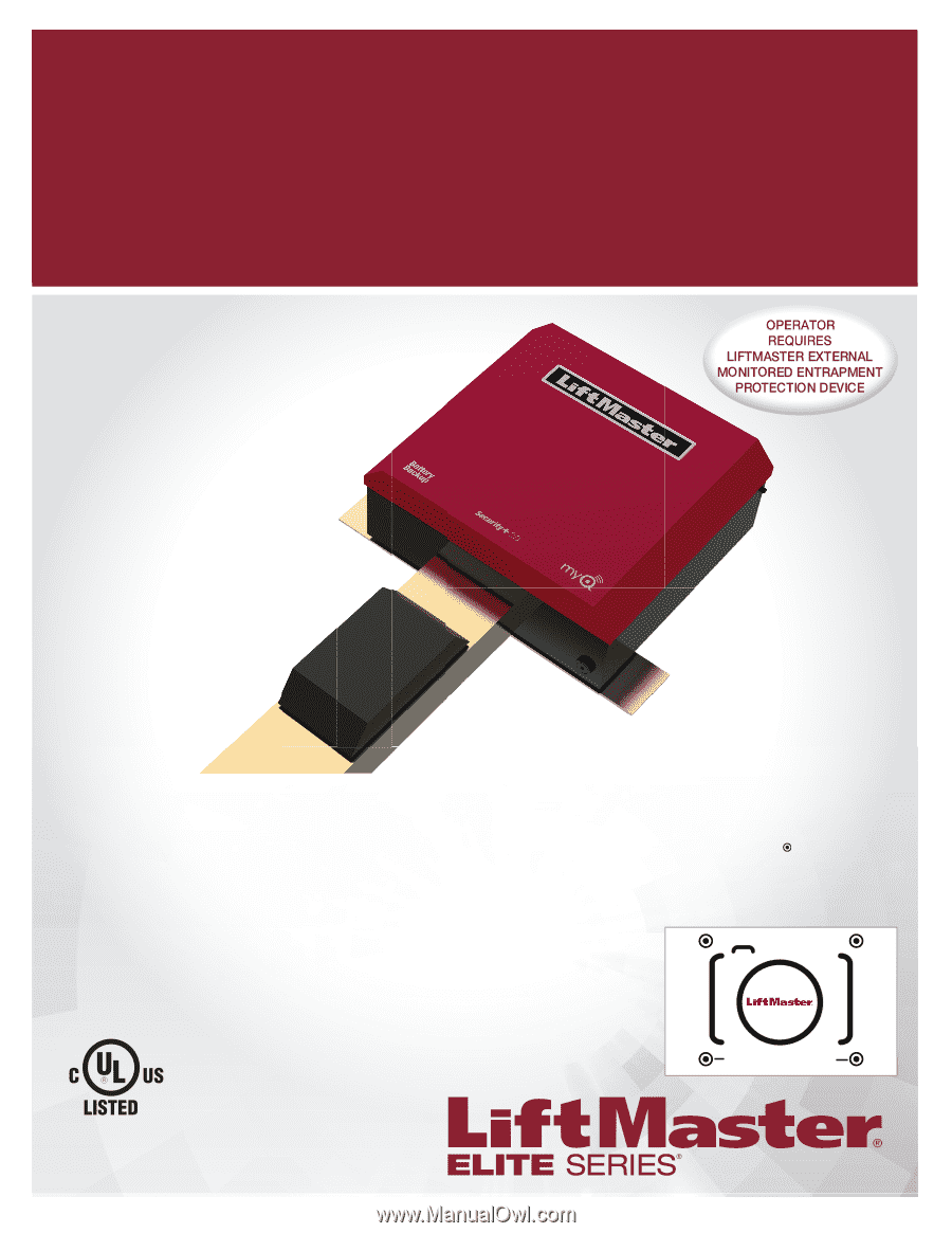
COMMERCIAL 24VDC HIGH TRAFFIC
OVERHEAD DOOR AND GATE OPERATOR
WITH BATTERY BACKUP
Model
HCTDCU
INSTALLATION MANUAL
LiftMaster
845 Larch Avenue
Elmhurst, IL 60126-1196
•
THIS PRODUCT IS TO BE INSTALLED AND SERVICED BY A
TRAINED TECHNICIAN ONLY.
•
This model is for use on vehicular passage gates or
commercial doors ONLY and not intended for use on
pedestrian passage gates.
•
Install the operator at least 8 feet (2.4 m) above the floor.
•
This model is intended for use in Class II, III and IV vehicular
trolley gate or commercial door applications.
•
Visit LiftMaster.com to locate a professional installing dealer
in your area.
•
This gate/door operator is compatible with MyQ
®
and
Security+ 2.0
®
accessories.
Register your operator to receive
updates and offers from LiftMaster
Take a photo of the camera icon
including the points (
).
Send it in by texting the photo to 71403
(US) or visit www.liftmaster.photo
(Global)
HCTDCU
Motor Unit
HCT08
8 Foot Rail
HCT10
10 Foot Rail
HCT12
12 Foot Rail
PHOTOREGISTER
SM
LM-HCTROLLEY