LiftMaster HCTDCU HCTDCU Installation Manual - Page 29
Custom Lights Or Anunciators, Party Radios, Red/green Light
 |
View all LiftMaster HCTDCU manuals
Add to My Manuals
Save this manual to your list of manuals |
Page 29 highlights
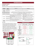
ACCESSORY WIRING RED/GREEN LIGHT Main control board The RGL24LY is a low power red/green LED light accessory used to indicate the door status where upward visibility is limited. The RGL24LY light control is directly powered from the main control board and is enabled by AUX 1 and AUX 2 switches on the expansion board. See table on page 31 for red/green light functionality. The RGL24LY will run when the operator is on battery backup power. WIRING: Expansion board 1. Connect the COM terminal of the RGL24LY light to the NEGATIVE (-) terminal of ACCESSORY POWER ON on the main board. 1 EYE ONLY 2 EYE/ EDGE 3 EYE/ EDGE COM OPEN CLOSE 2. Connect the RED terminal of the RGL24LY to the NORMALLY OPEN SBC (N.O.) terminal of AUX RELAY 1 on the expansion board. OPN CLS 3. Connect the GREEN terminal of the RGL24LY to the NORMALLY STP COM OPEN (N.O.) terminal of AUX RELAY 2 on the expansion board. 4. Connect the COM terminals of AUX RELAY 1 and 2 to the POSITIVE (+) terminal of ACCESSORY POWER ON on the main board. Wire not provided. CUSTOM LIGHTS OR ANUNCIATORS Other devices can be controlled by the AUX relays in red/green warning mode. These devices require their own power source which is switched from the AUX relays. AUX 1 and 2 provide N.O and N.C options and are rated to 10A. 3rd PARTY RADIOS POWER: 1. Make sure the radio is rated for 24 V (look at its nameplate or the transformer in use). 2. Check for AC or DC. 3a. AC, AC/DC, or no polarity: Connect power wires to the ACCESSORY POWER ON terminal of the main board. 3b. DC and shows polarity: Connect the positive wire to the positive (+) terminal of ACCESSORY POWER ON on the main board. Connect the negative wire to the negative (-) terminal of ACCESSORY POWER ON on the main board. 4. The ACC PWR OVLD LED on the main board will light if there is a problem with the radio. SIGNAL: 1. Locate the signal wires from the receiver. There may be one or two. 2a. For a single wire receiver: Connect to the positive(+) terminal of the desired input. 2b. For a 2 wire receiver: Connect to the positive(+) and negative (-) terminal of the desired input. For open-stop-close-stop operation: connect to the SBC terminal on the expansion board. For open only operation: connect to the OPEN terminal on the expansion board or the EXIT terminal on the main board. The Timer-to-Close (TTC) must be set to close the door, see page 24. Main control board (+) RELAY COMMON 24 V 29 RED COM GREEN RGL24LY red/green light 3rd Party Radio
-
 1
1 -
2
-
3
-
4
-
5
-
6
-
7
-
8
-
9
-
10
-
11
-
12
-
13
-
14
-
15
-
16
-
17
-
18
-
19
-
20
-
21
-
22
-
23
-
 24
24 -
 25
25 -
 26
26 -
 27
27 -
 28
28 -
 29
29 -
 30
30 -
 31
31 -
 32
32 -
 33
33 -
 34
34 -
35
-
36
-
37
-
38
-
39
-
40
-
41
-
42
-
43
-
44
-
45
-
46
-
47
-
48
-
49
-
50
-
51
-
52
-
53
-
54
-
55
-
56
-
57
-
58
-
59
-
60
-
61
-
62
-
63
-
64
-
65
-
66
-
67
-
68
-
69
-
70
-
71
-
72
-
73
-
74
-
75
-
76
-
77
-
78
-
79
-
80
-
81
-
82
-
83
-
84
-
85
-
86
-
87
-
88
-
89
-
90
-
91
-
92
 |
 |
