Lowrance Auto-Standby button Metal NAIS 400 Owners Manual
Lowrance Auto-Standby button Metal Manual
 |
View all Lowrance Auto-Standby button Metal manuals
Add to My Manuals
Save this manual to your list of manuals |
Lowrance Auto-Standby button Metal manual content summary:
- Lowrance Auto-Standby button Metal | NAIS 400 Owners Manual - Page 1
Isometric view NAIS-400 Class B AIS Transceiver User Manual ENGLISH www.bandg.com | www.simrad-yachting.com | www.lowrance.com - Lowrance Auto-Standby button Metal | NAIS 400 Owners Manual - Page 2
THIS PRODUCT IN A WAY THAT MAY CAUSE ACCIDENTS, DAMAGE OR THAT MAY VIOLATE THE LAW. Governing Language: This statement, any instruction manuals, user guides and other information relating to the product (Documentation) may be translated to, or has been translated from, another language (Translation - Lowrance Auto-Standby button Metal | NAIS 400 Owners Manual - Page 3
24 Introduction to proAIS2 26 Operation 26 Using the AIS transceiver 26 Switch functions 26 Using proAIS2 with your AIS transceiver 26 Indicator functions 28 Troubleshooting 29 Specifications 2 | Contents | NAIS-400 User Manual - Lowrance Auto-Standby button Metal | NAIS 400 Owners Manual - Page 4
NMEA 0183 data port 22 Figure 12 Connecting the power supply 27 Figure 13 Indicator location on the AIS transceiver unit Contents | NAIS-400 User Manual | 3 - Lowrance Auto-Standby button Metal | NAIS 400 Owners Manual - Page 5
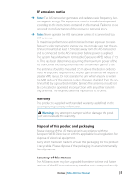
will have an AIS transceiver turned on, or installed. The performance of the transceiver may be seriously impaired if not installed as instructed in the user manual, or due to other factors such as weather and or nearby transmitting devices. Compatibility with other systems may vary and is reliant - Lowrance Auto-Standby button Metal | NAIS 400 Owners Manual - Page 6
: The AIS transceiver generates and radiates radio frequency electromagnetic energy. This equipment must be installed and operated according to the instructions contained in this manual. Failure to do so can result in malfunctioning of the receiver or personal injury. ¼¼ Note: Never operate the AIS - Lowrance Auto-Standby button Metal | NAIS 400 Owners Manual - Page 7
for consequences arising from omissions or inaccuracies in this manual and any other documentation provided with this product. Declaration energy and, if not installed and used in accordance with the instructions, may cause harmful interference to radio communications. This device complies with - Lowrance Auto-Standby button Metal | NAIS 400 Owners Manual - Page 8
est susceptible d'en compromettre le Fonctionnement. Cet appareil numérique de la classe B est conforme à la norme NMB-003 du Canada. Notices | NAIS-400 User Manual | 7 - Lowrance Auto-Standby button Metal | NAIS 400 Owners Manual - Page 9
vessel on which they are installed. • This NAIS-400 product is an AIS Class B transceiver. NAIS-400 8 | About your AIS class B transceiver | NAIS-400 User Manual - Lowrance Auto-Standby button Metal | NAIS 400 Owners Manual - Page 10
information about the vessel which must be programmed into the AIS transceiver. This includes: • Maritime Mobile Service Identity (MMSI) • Vessel name • Vessel call sign (if available) • Vessel type • Vessel their own vessel data. About your AIS class B transceiver | NAIS-400 User Manual | 9 - Lowrance Auto-Standby button Metal | NAIS 400 Owners Manual - Page 11
1 Items included with the product NN22Kkccabllee Support tools CD The CD supplied with the package versions of this manual. Quick start guide The quick start guide gives a handy one-page reference for the installation process. Product manual This document is the product manual and should be - Lowrance Auto-Standby button Metal | NAIS 400 Owners Manual - Page 12
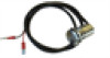
GGrreeeenn AAmmbbeer r RReedd BBluluee MouMnotuinntginghhoollees PowPeorwaenr adndddaatta VHVFHaFnatnetennnna GGPPSSanatnentenanna MMouunntitnignhgohleos les NNMMEEAA2020000 UUSSBB Figure 2 AIS transceiver overview About your AIS class B transceiver | NAIS-400 User Manual | 11 - Lowrance Auto-Standby button Metal | NAIS 400 Owners Manual - Page 13
NNMMEEAA 00118833 ddeevviiccee CChhaarrttppllootttteer UUSB NNAAIISS--440000 NNMMEEAA 2000 Figure 3 Electrical connections to the AIS transceiver 12 | About your AIS class B transceiver | NAIS-400 User Manual - Lowrance Auto-Standby button Metal | NAIS 400 Owners Manual - Page 14
-400 transceiver. The use of third party antenna splitters may result in malfunction or permanent damage to the NAIS-400 transceiver. Installation | NAIS-400 User Manual | 13 - Lowrance Auto-Standby button Metal | NAIS 400 Owners Manual - Page 15
your AIS transceiver to your chartplotter. Please refer to the user manual supplied with your chartplotter for details of how to connect and to your NMEA 2000 network via the supplied cable. Refer to your chartplotter manual for making NMEA 2000 connection. You may also need to enable the display - Lowrance Auto-Standby button Metal | NAIS 400 Owners Manual - Page 16
detailed in the previous section Preparing for installation. It is strongly recommended that you read all of the instructions in this manual prior to installation. If, after reading this manual, you are unsure about any element of the installation process, please contact your dealer for advice. The - Lowrance Auto-Standby button Metal | NAIS 400 Owners Manual - Page 17
direct path of a radar transmitter. To pole mount the external GPS antenna, you will require a 1-inch 14 TPI thread pole. 16 | Installation | NAIS-400 User Manual - Lowrance Auto-Standby button Metal | NAIS 400 Owners Manual - Page 18
area with the threaded rods engaging the 4 drilled mounting holes. • Use the 4 brass washers and nuts to secure the GPS antenna. Installation | NAIS-400 User Manual | 17 - Lowrance Auto-Standby button Metal | NAIS 400 Owners Manual - Page 19
, the external switch and the NMEA 0183 data ports. The cable has a pre-moulded connector at one end which should 18 | Installation | NAIS-400 User Manual - Lowrance Auto-Standby button Metal | NAIS 400 Owners Manual - Page 20
your wiring very carefully before applying power to the product. Failure to wire the product correctly could result in permanent damage. Installation | NAIS-400 User Manual | 19 - Lowrance Auto-Standby button Metal | NAIS 400 Owners Manual - Page 21
and in the diagram in Figure 11. Connect the wires to the appropriate connections on your NMEA 0183 compatible equipment. Please refer to your equipment manual for more information. The AIS transceiver has a high speed bi-directional port, which operates at 38,400 baud and a low speed bi-directional - Lowrance Auto-Standby button Metal | NAIS 400 Owners Manual - Page 22
. The USB drivers are installed as part of the proAIS2 installation process. Please install proAIS2 as described in section 4 before attempt- Installation | NAIS-400 User Manual | 21 - Lowrance Auto-Standby button Metal | NAIS 400 Owners Manual - Page 23
Port 1 38,400baud (chart plotter) Transmit + Transmit - Receive + Receive - NMEA0183 Port 2 4,800baud (other NMEA0183 device) Figure 12 Connecting the power supply Installation | NAIS-400 User Manual - Lowrance Auto-Standby button Metal | NAIS 400 Owners Manual - Page 24
been pre-configured, the amber and red indicators will be illuminated until the configuration process has been completed. Configuring your AIS transceiver | NAIS-400 User Manual | 23 - Lowrance Auto-Standby button Metal | NAIS 400 Owners Manual - Page 25
. Now follow the on-screen prompts. 2. If a security warning appears, click 'Install' to continue with the installation. 24 | Configuring your AIS transceiver | NAIS-400 User Manual - Lowrance Auto-Standby button Metal | NAIS 400 Owners Manual - Page 26
change the MMSI for any reason, please contact your dealer who will arrange to have the MMSI reset. Configuring your AIS transceiver | NAIS-400 User Manual | 25 - Lowrance Auto-Standby button Metal | NAIS 400 Owners Manual - Page 27
your chartplotter to make use of the AIS transceiver features will be given in your chartplotter manual. If you are using charting software running on a PC, please refer to the instructions provided with your chartplotting software for details of how to configure it to display AIS information - Lowrance Auto-Standby button Metal | NAIS 400 Owners Manual - Page 28
error. The likely causes of this are detailed in the troubleshooting guide in chapter 6. Diagnostic messages displayed in proAIS2 may also help troubleshoot the cause of the error. Amber and blue indicators When (via an AIS base station) to cease transmissions. Operation | NAIS-400 User Manual | 27 - Lowrance Auto-Standby button Metal | NAIS 400 Owners Manual - Page 29
6 Troubleshooting Issue Possible cause and remedy No data is being received by the chartplotter • Check . If the guidance given in the table above does not rectify the problem you are experiencing, please contact your dealer for further assistance. 28 | Troubleshooting | NAIS-400 User Manual - Lowrance Auto-Standby button Metal | NAIS 400 Owners Manual - Page 30
Less than -107 dBm at 20% PER Co-channel 10 dB Adjacent channel 70 dB IMD 65 dB Blocking 84 dB Specifications | NAIS-400 User Manual | 29 - Lowrance Auto-Standby button Metal | NAIS 400 Owners Manual - Page 31
- Luxembourg CH - Switzerland FR - France MT - Malta TR - Turkey DE - Germany NL - Netherlands UK - United Kingdom GR - Greece NO - Norway 30 | Specifications | NAIS-400 User Manual - Lowrance Auto-Standby button Metal | NAIS 400 Owners Manual - Page 32
201-0320:2 NAIS-400 Product Manual www.bandg.com www.simrad-yachting.com www.lowrance.com *988-10373-002*
-
 1
1 -
 2
2 -
 3
3 -
 4
4 -
 5
5 -
 6
6 -
 7
7 -
8
-
9
-
10
-
11
-
12
-
13
-
14
-
15
-
16
-
17
-
18
-
19
-
20
-
21
-
22
-
23
-
24
-
25
-
26
-
27
-
28
-
29
-
30
-
31
-
32
 |
 |

ENGLISH
NAIS-400 Class B
AIS Transceiver
User Manual
www.bandg.com | www.simrad-yachting.com | www.lowrance.com