Lowrance Auto-Standby button Metal NAIS 400 Owners Manual - Page 12
The AIS transceiver has an external GPS antenna. You should ensure
 |
View all Lowrance Auto-Standby button Metal manuals
Add to My Manuals
Save this manual to your list of manuals |
Page 12 highlights
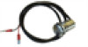
AIS transceiver unit Figure 2 shows an overview of the AIS transceiver unit. The AIS transceiver has a number of indicators which provide information to the user about the status of the AIS transceiver. Please refer to Indicator functions, chapter 5 for more details. The AIS transceiver has an external GPS antenna. You should ensure that the GPS antenna is mounted where it has a clear view of the sky. Fig. 2 Overview Power and data cable The power and data cable connects to the AIS transceiver and enables connection to power, NMEA 0183 and an external silent mode switch. InInddiiccaattoorrlligighhtsts GGrreeeenn AAmmbbeer r RReedd BBluluee MouMnotuinntginghhoollees PowPeorwaenr adndddaatta VHVFHaFnatnetennnna GGPPSSanatnentenanna MMouunntitnignhgohleos les NNMMEEAA2020000 UUSSBB Figure 2 AIS transceiver overview About your AIS class B transceiver | NAIS-400 User Manual | 11
-
 1
1 -
2
-
3
-
4
-
5
-
6
-
 7
7 -
 8
8 -
 9
9 -
 10
10 -
 11
11 -
 12
12 -
 13
13 -
 14
14 -
 15
15 -
 16
16 -
 17
17 -
18
-
19
-
20
-
21
-
22
-
23
-
24
-
25
-
26
-
27
-
28
-
29
-
30
-
31
-
32
 |
 |
