Lowrance Auto-Standby button Metal NAIS 400 Owners Manual - Page 20
Warning, Wire colour, Description, Function
 |
View all Lowrance Auto-Standby button Metal manuals
Add to My Manuals
Save this manual to your list of manuals |
Page 20 highlights
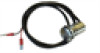
be connected to the connector on the unit marked 'PWR/DATA'. The other end of the cable has eight colour-coded bare wires ready for connection. The table below lists the function of each colour-coded wire for reference. Wire colour Red Black Light green Orange Brown Blue White Green Purple Pink Grey Yellow Pin no. Description Function 8 Power in + 9 Power in - Power supply connections 12 V to a24 V DC 12 Switch input10 Switch input+ External switch connection for silent mode 1 NMEA 0183 port 1 TX+ (Transmit +) 2 NMEA 0183 port 1 TX- (Transmit -) High speed NMEA 0183 - Port 1: (38,400 baud) 3 NMEA 0183 port 1 RX+ (Receive +) intended for connection to chartplotters 4 NMEA 0183 port 1 RX- (Receive -) 11 NMEA 0183 port 2 TX+ (Transmit +) 7 NMEA 0183 port 2 TX- (Transmit -) Low speed NMEA 0183 - Port 2: (4,800 baud) intended for connection 6 NMEA 0183 port 2 RX+ (Receive +) to other NMEA 0183 compatible devices 5 NMEA 0183 port 2 RX- (Receive -) Colour-coding of wires in the accessory cable Warning: Please check your wiring very carefully before applying power to the product. Failure to wire the product correctly could result in permanent damage. Installation | NAIS-400 User Manual | 19
-
 1
1 -
2
-
3
-
4
-
5
-
6
-
7
-
8
-
9
-
10
-
11
-
12
-
13
-
14
-
 15
15 -
 16
16 -
 17
17 -
 18
18 -
 19
19 -
 20
20 -
 21
21 -
 22
22 -
 23
23 -
 24
24 -
 25
25 -
26
-
27
-
28
-
29
-
30
-
31
-
32
 |
 |
