Lowrance Auto-Standby button Metal NAIS 400 Owners Manual - Page 4
Table of figures, AIS transceiver dimensions
 |
View all Lowrance Auto-Standby button Metal manuals
Add to My Manuals
Save this manual to your list of manuals |
Page 4 highlights
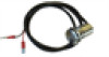
Table of figures 10 Figure 1 Items included with the product 11 Figure 2 AIS transceiver overview 12 Figure 3 Electrical connections to the AIS transceiver 13 Figure 4 Typical installation configuration 16 Figure 5 AIS transceiver dimensions 16 Figure 6 AIS transceiver mounting 17 Figure 7 GPS antenna mounting 18 Figure 8 Position of the GPS antenna connector 18 Figure 9 Position of the VHF antenna connector 20 Figure 10 Connecting an external switch 21 Figure 11 Connecting to the NMEA 0183 data port 22 Figure 12 Connecting the power supply 27 Figure 13 Indicator location on the AIS transceiver unit Contents | NAIS-400 User Manual | 3
-
 1
1 -
 2
2 -
 3
3 -
 4
4 -
 5
5 -
 6
6 -
 7
7 -
 8
8 -
 9
9 -
 10
10 -
11
-
12
-
13
-
14
-
15
-
16
-
17
-
18
-
19
-
20
-
21
-
22
-
23
-
24
-
25
-
26
-
27
-
28
-
29
-
30
-
31
-
32
 |
 |

| 3
Contents |
NAIS-400 User Manual
Table of figures
10
Figure 1
Items included with the product
11
Figure 2
AIS transceiver overview
12
Figure 3
Electrical connections to the AIS transceiver
13
Figure 4
Typical installation configuration
16
Figure 5
AIS transceiver dimensions
16
Figure 6
AIS transceiver mounting
17
Figure 7
GPS antenna mounting
18
Figure 8
Position of the GPS antenna connector
18
Figure 9
Position of the VHF antenna connector
20
Figure 10
Connecting an external switch
21
Figure 11
Connecting to the NMEA 0183 data port
22
Figure 12
Connecting the power supply
27
Figure 13
Indicator location on the AIS transceiver unit