MSI 845GEM-L User Guide
MSI 845GEM-L - Motherboard - Micro ATX Manual
 |
View all MSI 845GEM-L manuals
Add to My Manuals
Save this manual to your list of manuals |
MSI 845GEM-L manual content summary:
- MSI 845GEM-L | User Guide - Page 1
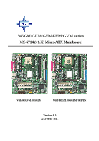
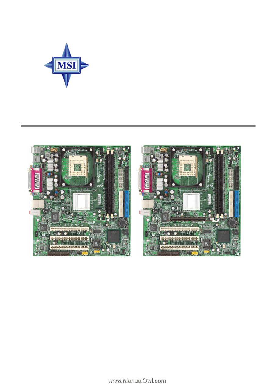
845GM/GLM/GEM/PEM/GVM series MS-6714 (v1.X) Micro ATX Mainboard With 845GVM / 845GLM With 845GM / 845GEM / 845PEM Version 1.0 G52-M6714X1 i - MSI 845GEM-L | User Guide - Page 2
compliance could void the user's authority to operate the equipment. Notice 2 Shielded interface cables and A.C. power cord, if any, must be used in order to comply with the emission limits. VOIR LA NOTICE D'INSTALLATION AVANT DE RACCORDER AU RESEAU. Micro-Star International MS-6714 Tested to comply - MSI 845GEM-L | User Guide - Page 3
Support If a problem arises with your system and no solution can be obtained from the user's manual, please contact your place of purchase or local distributor. Alternatively, please try the following help resources for further guidance. Visit the MSI website for FAQ, technical guide, BIOS updates - MSI 845GEM-L | User Guide - Page 4
the safety instructions carefully. 2. Keep this User's Manual for future reference. 3. Keep this equipment away from humidity. 4. Lay this equipment on a reliable flat surface before setting it up. 5. The openings on the enclosure are for air convection hence protects the equipment from overheating - MSI 845GEM-L | User Guide - Page 5
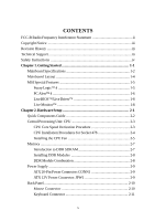
Instructions iv Chapter 1. Getting Started 1-1 Mainboard Specifications 1-2 Mainboard Layout 1-4 MSI Special Features 1-5 Fuzzy Logic™ 4 1-5 PC Alert™ 4 1-6 Live BIOS™/Live Driver 1-8 Live Monitor 1-8 Chapter 2. Hardware Setup 2-1 Quick Components Guide 2-2 Central Processing Unit: CPU - MSI 845GEM-L | User Guide - Page 6
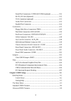
2-12 RJ-45 LAN Jack (Optional 2-12 VGA Connector (optional 2-13 Audio Port Connectors 2-13 Parallel Front Panel Connectors: JFP1 & JFP2 2-20 Front Panel Audio Connector: JAUDIO1 2-21 Front USB Connectors: Interrupt Request Routing 2-25 Chapter 3. BIOS Setup 3-1 Entering Setup 3-2 Control - MSI 845GEM-L | User Guide - Page 7
Advanced Chipset Features 3-12 Integrated Peripherals 3-15 Power Management Setup 3-19 PNP/PCI Configurations 3-23 PC Health Status 3-25 Frequency/Voltage Control 3-26 Load Fail-Safe/Optimized Defaults 3-28 Set Supervisor/User Password 3-29 Troubleshooting T-1 Glossary ...G-1 vii - MSI 845GEM-L | User Guide - Page 8
/PEM/ GVM series (MS-6714 v1.X) Micro ATX mainboard. The 845GM/ GLM/GEM/PEM/GVM series are based on Intel® 845G (B Step) /845GL/845GE/845PE/845GV GMCH & ICH4 chipsets and provides 6 USB 2.0 ports for high-speed data transmission and one SPDIF pinheader for digital audio transmission. With all these - MSI 845GEM-L | User Guide - Page 9
M-ATX Mainboard Mainboard Specifications CPU h Support Intel® P4 Northwood (Socket 478) processor. h Support 533MHz or 400MHz FSB. h Support 3.2GHz or higher speed P4 processor. Chipset h Intel® 845G (B Step) /845GL/845GE/845PE/845GV GMCH chipset (760 mBGA) - Support FSB 400MHz (845GL) /533MHz - MSI 845GEM-L | User Guide - Page 10
BIOS for 845GE/PE. h ACPI, SMBIOS 2.3, Green and Boot Block. h Provides DMI 2.0, WFM 2.0, WOL, WOR, chassis intrusion, and SMBus for system management. Dimension h Micro-ATX Form Factor: 24.5 cm (L) x 21.4 cm (W). Mounting h 6 mounting holes. Others h Suspend to RAM/ Disk function h HW monitoring - MSI 845GEM-L | User Guide - Page 11
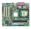
keyboard USB ports JPW1 Top : Parallel Port Bo tt om : COM A VGA port CP UFAN1 Top: LAN Jack Bottom: USB ports Mic Line-In Line-Out JCOM2 JCASE IR1 Winbond Slot 2 PCI Slot 3 JAUDIO1 AUX_IN1 BIOS JUSB1 ICH4 J B AT 1 SYSFAN1 JFP2 JFP1 (MS-6714 v1.X) Micro ATX Mainboard IDE 2 IDE 1 1-4 - MSI 845GEM-L | User Guide - Page 12
Web site. z CPU Speed allows users to adjust the CPU speed through CPU Multiplier and FSB. z Voltage allows user to adjust the voltage of CPU/Memory/AGP. z MSI Info provides information about the mainboard, BIOS and OS. z CPU Info provides detailed information about the CPU. z CPU Fan Speed - MSI 845GEM-L | User Guide - Page 13
disk. The utility is just like your PC doctor that can detect the following PC hardware status during real time operation: Ø monitor CPU & system temperatures Ø monitor fan speeds Ø monitor system voltages If one of the items above is abnormal, the program main screen will be immediately shown on - MSI 845GEM-L | User Guide - Page 14
the Cute skin (as shown below) with information about the CPU and chipset. Right-click the mouse to select the skin you want to switch to. Cute MSI Reminds You... The new feature COOLER XP will work only if your mainboard supports AMD Athlon XP CPU. Items shown on PC Alert 4 vary depending on your - MSI 845GEM-L | User Guide - Page 15
VGA BIOS - Updates the VGA BIOS online. z Live VGA Driver - Updates the VGA driver online. z Live Utility - Updates the utilities online. If the product you purchased does not support any of the functions listed above, a "sorry" message is displayed. For more information on the update instructions - MSI 845GEM-L | User Guide - Page 16
BIOS/drivers version on the MSI Web site. To use the function, you need to install the "MSI Live Update Series 2" application. After the installation, the "MSI Live Monitor the BIOS/drivers version, or change the LAN settings right from the dialog box. You can right-click the MSI Live Monitor icon - MSI 845GEM-L | User Guide - Page 17
Chapter 2. Hardware Setup Hardware Setup This chapter tells you how to install the CPU, memory modules, and expansion cards, as well as how to setup the jumpers on the mainboard. Also, it provides the instructions on connecting the peripheral devices, such as the mouse, keyboard, etc. While doing - MSI 845GEM-L | User Guide - Page 18
845 GM/GLM/GEM/PEM/GVM series M-ATX Mainboard Quick Components Guide JPW1, p.2-9 CPU, p.2-3 CFAN1, p.2-17 DDR DIMMs, p.2-7 Back Panel I/O, p.2-11 JCOM2, p.2-11 JCASE, p.2-19 IR1, 24 JBAT1, p.2-23 SYSFAN1, p.2-17 JAUDIO1, p.2-21 JUSB1, p.2-22 AUX_IN1, p.2-18 JFP1, p.2-20 JFP2, p.2-20 2-2 - MSI 845GEM-L | User Guide - Page 19
Hardware Setup Central Processing Unit: CPU The mainboard supports Intel® Pentium® 4 Northwood processor in the 478 pin package. The mainboard uses a CPU socket called PGA478 for easy CPU installation. When you are installing the CPU, make sure the CPU has a heat sink and a cooling fan attached on - MSI 845GEM-L | User Guide - Page 20
the lever up to a 90degree angle. 3. Look for the gold arrow. The gold arrow should point towards the lever pivot. The CPU can only fit in the correct orientation. 4. If the CPU is correctly installed, the pins should be completely embedded into the socket and can not be seen. Please note that any - MSI 845GEM-L | User Guide - Page 21
important. To dissipate heat, you need to attach the CPU cooling fan and heatsink on top of the CPU. Follow the instructions below to install the Heatsink/Fan: 1. Locate the CPU and its retention mechanism on the motherboard. retention mechanism 2. Position the heatsink onto the retention - MSI 845GEM-L | User Guide - Page 22
845 GM/GLM/GEM/PEM/GVM series M-ATX Mainboard 5. fan power cable NOTES 2-6 - MSI 845GEM-L | User Guide - Page 23
Setup Memory The mainboard provides 2 slots for 184-pin DDR SDRAM DIMM (Double In-Line Memory Module) modules and supports the memory size up to 2GB. You can install PC2700/DDR333 (for 845GE) or PC2100/DDR266 (for 845GV) modules on the DDR DIMM slots (DDR 1~2). DDR DIMM Slots (DDR 1&2, from right to - MSI 845GEM-L | User Guide - Page 24
2 & 3) Memory Module S/D S/D Maximum System Memory Supported Total Memory 64MB~1GB 64MB~1GB 64MB~2GB S: Single on the center of module. The module will only fit in the right orientation. 2. Insert the DIMM memory module is deeply inserted in the socket. MSI Reminds You... You can barely see the - MSI 845GEM-L | User Guide - Page 25
supports ATX power supply for the power system. Before inserting the power supply connector, always make sure that all components are installed properly to ensure that no damage will be caused. ATX 20 used to provide power to the CPU. 11 1 3 4 1 2 JPW1 20 10 CONN1 JPW1 Pin Definition PIN - MSI 845GEM-L | User Guide - Page 26
GM/GLM/GEM/PEM/GVM series M-ATX Mainboard Back Panel The back panel provides the following connectors: Mouse USB Ports Parallel LAN (Optional) MIC Keyboard COMA VGA Port USB Ports L-in L-out Mouse Connector The mainboard provides a standard PS/2® mouse mini DIN connector for attaching a PS - MSI 845GEM-L | User Guide - Page 27
Hardware Setup Keyboard Connector The mainboard provides a standard PS/2® keyboard mini DIN connector for attaching a PS/2® keyboard. You can plug a PS/2® keyboard directly into this connector. 6 5 4 3 2 1 PS/2 Keyboard (6-pin Female) Pin Definition PIN SIGNAL DESCRIPTION 1 Keyboard - MSI 845GEM-L | User Guide - Page 28
Jack (Optional) The mainboard provides one standard RJ-45 jack for connection to Local Area Network (LAN). You can connect a network cable to the LAN jack. RJ-45 LAN Jack Pin Definition PIN SIGNAL 1 TDP 2 TDN 3 RDP 4 NC 5 NC 6 RDN 7 NC 8 NC DESCRIPTION Transmit Differential Pair - MSI 845GEM-L | User Guide - Page 29
microphones. Line in 1/8" Stereo Audio Connectors Line out MIC MSI Reminds You... For advanced audio application, RealTek ALC650 audio chip is provided to offer support for 6-channel audio operation and can turn rear audio connectors from 2-channel to 4-/6-channel audio. For more information on - MSI 845GEM-L | User Guide - Page 30
centronic connector as LPT. A parallel port is a standard printer port that supports Enhanced Parallel Port (EPP) and Extended Capabilities Parallel Port (ECP) mode. Select In 18 GND Ground 19 GND Ground 20 GND Ground 21 GND Ground 22 GND Ground 23 GND Ground 24 GND Ground 25 - MSI 845GEM-L | User Guide - Page 31
mainboard provides connectors to connect to FDD, IDE HDD, case, modem, LAN, USB Ports, IR module and CPU/System/Power Supply FAN. Floppy Disk Drive Connector: FDD1 The mainboard provides a standard floppy disk drive connector that supports 360K, 720K, 1.2M, 1.44M and 2.88M floppy disk types. FDD1 - MSI 845GEM-L | User Guide - Page 32
connect up to four hard disk drives, CD-ROM, 120MB Floppy (reserved for future BIOS) and other devices. IDE2 IDE1 IDE1 (Primary IDE Connector) The first hard drive IDE Connector) IDE2 can also connect a Master and a Slave drive. MSI Reminds You... If you install two hard disks on cable, you must - MSI 845GEM-L | User Guide - Page 33
System Hardware Monitor chipset on-board, you must use a specially designed fan with speed sensor to take advantage of the CPU fan control. GND +12V SENSOR CPUFAN1 SENSOR +12V GND SYSFAN1 MSI Reminds You... 1. Always consult the vendors for proper CPU cooling fan. 2. CPUFAN1 supports the fan control - MSI 845GEM-L | User Guide - Page 34
845 GM/GLM/GEM/PEM/GVM series M-ATX Mainboard CD-In Connector: CD_IN1 The connector is for CD-ROM audio connector. Aux Line-In Connector: AUX_IN1 The connector is for DVD add-on card with Line-in connector. R GND L CD_IN1 R GND L AUX_IN1 2-18 - MSI 845GEM-L | User Guide - Page 35
you to connect to IrDA Infrared module. You must configure the setting through the BIOS setup to use the IR function. JIR1 is compliant with Intel® Front Panel I/O Connectivity Design Guide. 1 2 5 6 IR1 IR1 Pin Definition Pin Signal 1 NC 2 NC 3 VCC5 4 GND 5 IRTX 6 IRRX Chassis - MSI 845GEM-L | User Guide - Page 36
connection to the front panel switches and LEDs. JFP1 is compliant with Intel® Front Panel I/O Connectivity Design Guide. Power Power LED Switch 2 1 10 9 JFP1 HDD Reset LED Switch 2-20 Speaker 87 Power JFP2 LED 21 JFP1 Pin Definition PIN SIGNAL 1 HD_LED_P 2 FP PWR/SLP 3 HD_LED_N - MSI 845GEM-L | User Guide - Page 37
connect to the front panel audio and is compliant with Intel® Front Panel I/O Connectivity Design Guide. 2 10 1 9 JAUDIO1 Left channel audio signal to front panel Left channel audio signal return from front panel MSI Reminds You... If you don't want to connect to the front audio header, pins - MSI 845GEM-L | User Guide - Page 38
compliant with Intel® I/O Connectivity Design Guide. USB 2.0 technology increases data transfer rate up to a maximum throughput of 480Mbps, which is 40 times faster than USB 1.1, and is ideal USB1- 5 USB0+ 6 USB1+ 7 GND 8 GND 9 Key 10 USBOC 9 1 10 2 JUSB1 (USB 2.0/Intel spec) 2-22 - MSI 845GEM-L | User Guide - Page 39
. With the CMOS RAM, the system can automatically boot OS every time it is turned on. If you want to clear the system configuration, use the JBAT1 (Clear CMOS Jumper ) to clear data. Follow the instructions below to clear the data: 1 JBAT1 1 1 3 Keep Data 3 Clear Data MSI Reminds You... You - MSI 845GEM-L | User Guide - Page 40
845GE BIOS configuration. CNR (Communication Network Riser) The CNR slot allows you to insert the CNR expansion cards. CNR is a specially designed network, audio, or modem riser card for ATX family motherboards. Its main processing is done through software and controlled by the motherboard's chipset - MSI 845GEM-L | User Guide - Page 41
Hardware Setup PCI Interrupt Request Routing The IRQ, abbreviation of interrupt request line and pronounced I-R-Q, are hardware lines over which devices can send interrupt signals to the microprocessor. The PCI IRQ pins are typically connected to the PCI bus INT A# ~ INT D# pins as follows: PCI - MSI 845GEM-L | User Guide - Page 42
This chapter provides information on the BIOS Setup program and allows you to configure the system for optimum use. You may need to run the Setup program when: ” An error message appears - MSI 845GEM-L | User Guide - Page 43
845 GM/GLM/GEM/PEM/GVM series M-ATX Mainboard Entering Setup Power on the computer and the system will start POST (Power On Self Test) process. When the message below appears on the screen, press key to enter Setup. Press DEL to enter SETUP If the message disappears before you respond and you - MSI 845GEM-L | User Guide - Page 44
and the possible selections for the highlighted item. Press to exit the Help screen. MSI Reminds You... The items under each BIOS category described in this chapter are under continuous update for better system performance. Therefore, the description may be slightly different from the latest - MSI 845GEM-L | User Guide - Page 45
to accept or enter the sub-menu. Standard CMOS Features Use this menu for basic system configurations, such as time, date etc. Advanced BIOS Features Use this menu to setup the items of Award® special enhanced features. Advanced Chipset Features Use this menu to change the values in the - MSI 845GEM-L | User Guide - Page 46
Load Optimized Defaults Use this menu to load factory default settings into the BIOS for stable system performance operations. Set Supervisor Password Use this menu to set Supervisor Password. Set User Password Use this menu to set User Password. Save & Exit Setup Save changes to CMOS and exit setup - MSI 845GEM-L | User Guide - Page 47
1 to 31 can be keyed by numeric function keys. year The year can be adjusted by users. Time The time format is . IDE Primary/Secondary Master/Slave Press PgUp/ or PgDn/ to select Manual, None or Auto type. Note that the specifications of your drive must match with the - MSI 845GEM-L | User Guide - Page 48
BIOS Setup ing items. Enter the information directly from the ., 2. 88M, 3.5 in. Video The setting controls the type of video adapter used for the primary monitor of the system. Available options: EGA/VGA , CGA 40, CGA 80, MONO. Halt On The setting determines whether the system will stop if an - MSI 845GEM-L | User Guide - Page 49
. MSI Reminds You... Enabling the functionality of Hyper-Threading Technology for your computer system requires ALL of the following platform Components: *CPU: An Intel® Pentium® 4 Processor with HT Technology; *Chipset: An Intel® Chipset that supports HT Technology; *BIOS: A BIOS that supports HT - MSI 845GEM-L | User Guide - Page 50
BIOS Setup CPU Hyper-Threading (for 845PE/GE/GV/G chipsets only) This field is used to enable or disable ZIP The system will boot from ATAPI ZIP drive. LAN The system will boot from the Network drive. Disabled Disable this sequence. MSI Reminds You... Available settings for "1st/2nd/3rd Boot - MSI 845GEM-L | User Guide - Page 51
or chipset hardware. Settings: 6, 8, 10, 12, 15, 20, 24 and 30. Typematic Delay (Msec) BIOS password protection that is implemented. Settings are described below: Option Setup System Description The password prompt appears only when end users try to run Setup. A password prompt appears every time - MSI 845GEM-L | User Guide - Page 52
BIOS Setup APIC Mode This field is used to enable or disable the APIC (Advanced Programmable Interrupt Controller). Due to compliance to PC2001 design guide used for the operating system. You need to select the MPS version supported by your operating system. To find out which version to use, consult - MSI 845GEM-L | User Guide - Page 53
chipset. Configure DRAM Timing Selects whether DRAM timing is controlled by the SPD (Serial Presence Detect) EEPROM on the DRAM module. Setting to By SPD enables DRAM timings to be determined by BIOS based on the configurations on the SPD. Selecting Manual allows users to configure the DRAM timings - MSI 845GEM-L | User Guide - Page 54
Prior to Thermal When the CPU temperature reaches a factory preset level, a thermal monitoring mechanism will be enabled following the appropriate timing delay specified in this field. With the thermal monitoring enabled, clock modulation controlled by the processor's internal thermal sensor is also - MSI 845GEM-L | User Guide - Page 55
Setting The following items allow you to configure the settings about On-Chip VGA. On-Chip VGA This setting allows you to enable or disable the on-chip VGA function.Setting: Enabled and Disabled. On-Chip VGA Frame Buffer Size The field specifies the size of system memory allocated for video memory - MSI 845GEM-L | User Guide - Page 56
BIOS Setup On-Chip Primary/Secondary PCI IDE The integrated peripheral controller contains an IDE interface with support supports it and the operating environment includes a DMA driver (Windows 95 OSR2 or a third-party IDE bus master driver). If your hard drive and your system software both support - MSI 845GEM-L | User Guide - Page 57
support or have any USB driver installed, such as DOS and SCO Unix. AC'97 Audio Auto allows the mainboard to detect whether an audio Disabled. Onboard LAN selection The field determines whether the onboard LAN controller is activated Option Description Auto BIOS will automatically determine - MSI 845GEM-L | User Guide - Page 58
BIOS Setup Serial Port A/B These items specify the base I/O port addresses of the onboard Serial Setting options: Hi,Hi, Hi,Lo, Lo,Hi, Lo,Lo. IR Transmission Delay This setting determines whether the IR transmission rate will be delayed while converting to receiving mode. Setting options: Disabled, - MSI 845GEM-L | User Guide - Page 59
Mode Use DMA The ECP mode has to use the DMA channel, so after the user chooses the onboard parallel port with the ECP feature, the setting "ECP Mode User DMA" should be set. At this time, the user can choose between DMA channel 3 or 1. Onboard Game Port This item is used to specify - MSI 845GEM-L | User Guide - Page 60
Management Setup MSI Reminds You... S3-related functions described in this section are available only when your BIOS supports S3 sleep sleep mode is a low power state. In this state, no system context (CPU or chipset) is lost and hardware maintains all system context. S3/STR The S3 sleep mode - MSI 845GEM-L | User Guide - Page 61
users to configure each mode separately. Min Saving Minimum Power Management. Suspend Mode = 1 Hour, and HDD Power Down = 15 Min. Max Time Out After the selected period of system inactivity, all devices except the CPU shut off. Settings: Disabled, 1 Min, 2 Min, 4 Min, 8 Min, 10 Min, 12 Min, 20 - MSI 845GEM-L | User Guide - Page 62
) to which it will slow down when the CPU reaches the predetermined overheat temperature. Settings range from 12.5% to 87.5% at 12.5% increment. Resume by RTC Alarm The field is used to enable or disable the feature of booting up the system on a scheduled time/date. Date (of Month) Alarm The field - MSI 845GEM-L | User Guide - Page 63
845 GM/GLM/GEM/PEM/GVM series M-ATX Mainboard Last State Restores the system to the status before power failure or interrupt occurred.enters the suspend/sleep mode, but if the button is pressed for more than four seconds, the computer is turned off. Reload Global Timer Events: Primary Master/ - MSI 845GEM-L | User Guide - Page 64
CPU itself uses when communicating with its special components. This section covers some very technical items and it is strongly recommended that only experienced users Award Plug and Play BIOS has the capacity to /98. If you set this field to "manual" choose specific resources by going into each of - MSI 845GEM-L | User Guide - Page 65
set to Manual. Press and you will enter the sub-menu of the items. IRQ Resources list IRQ 3/4/5/7/9/10/11/12/14/15 for users to set for further request. PCI/VGA Palette Snoop When set to Enabled, multiple VGA devices operating on different buses can handle data from the CPU on each set of - MSI 845GEM-L | User Guide - Page 66
BIOS Setup PC Health Status This section shows the status of your CPU, fan, overall system status, etc. Monitor function is available only if there is hardware monitoring mechanism onboard. Current System Temp., Current CPU Temperature, CPU Disabled. CPU Critical Temperature If the CPU temperature - MSI 845GEM-L | User Guide - Page 67
CPU Ratio Selection This setting controls the multiplier that is used to determine the internal clock speed of the processor relative to the external or motherboard to flatter curves. If you do not have any EMI problem, leave the setting at Disabled for optimal system stability and performance - MSI 845GEM-L | User Guide - Page 68
BIOS Setup and PCI bus. It provides a method for end users to overclock the processor. If the item shows Default, the setting will use the default value for the clock frequency of CPU host bus, AGP and PCI bus. 3-27 - MSI 845GEM-L | User Guide - Page 69
845 GM/GLM/GEM/PEM/GVM series M-ATX Mainboard Load Fail-Safe/Optimized Defaults The two options on the main menu allow users to restore all of the BIOS settings to the default Fail-Safe or Optimized values. The Optimized Defaults are the default values set by the mainboard manufacturer specifically - MSI 845GEM-L | User Guide - Page 70
prompted to enter it every time you try to enter BIOS Feature menu. If the Security Option is set to System, the password is required both at boot and at entry to Setup. If set to Setup, password prompt only occurs when you try to enter Setup. MSI Reminds You... About Supervisor Password & User - MSI 845GEM-L | User Guide - Page 71
number beside it. 2. At the back cover of the user's manual. Q: What do you mean by PCB version 1? A: PCB is printed circuit board. Saying PCB version 1 is the same as saying motherboard version 1. Q: Why my motherboard BIOS sticker is "Phoenix BIOS" but when I boot up my system I saw that "Award - MSI 845GEM-L | User Guide - Page 72
that you do NOT connect those described CPU fan directly to your motherboard, as it draws so much power, that Live Update Series support WinXP? A: Live Update Series version 215 can support WinXP. Download it from http:/ /www.msi.com.tw/support/liveupdate/livedriver.htm Q: After flashing the BIOS - MSI 845GEM-L | User Guide - Page 73
BIOS will be worth it. A word of advice, though, do not upgrade to the new BIOS, unless you really have to. Q: How do I update the BIOS? A: Please refer to http://www.msi.com.tw/support/bios to BIOS maker as A = AMI(R) W = AWARD(R) P = PHOENIX (R). 2nd digit refers to the internal chipset code. 3rd - MSI 845GEM-L | User Guide - Page 74
.ROM Insert this floppy disk in the floppy drive. Turn On the system and press and hold Ctrl-Home to force update. It will read the AMIBOOT.ROM file and recover the BIOS from the A drive. When 4 beeps are heard you may remove the floppy disk and restart the computer. For Award - MSI 845GEM-L | User Guide - Page 75
can fully support ACPI to allow users managing BIOS is stored in a ROM chip. Bus A set of hardware lines within the computer system, through which the data is transferred among different components. In a PC, the term bus usually refers to a local bus that connects the internal components to the CPU - MSI 845GEM-L | User Guide - Page 76
unit of time recognized by a device. For personal computers, clock cycles generally refer to the main system clock, which runs at 66 MHz. This means that there are 66 million clock cycles per second. Since modern CPUs run much faster (up to 533 MHz), the CPU can execute several instructions in - MSI 845GEM-L | User Guide - Page 77
Code types of ROM, EEPROM is not as fast as RAM. EEPROM is similar to flash memory (sometimes called part as an open alternative to the proprietary Micro Channel Architecture (MCA) that IBM introduced in PnP) devices in the BIOS. Windows and the BIOS access the ESCD area each time you re-boot your - MSI 845GEM-L | User Guide - Page 78
supports data transfer rates of up to 400 Mbps for connecting up to 63 external devices. Internal common problem when motherboard. It allows 16 bits at a time to flow between the motherboard circuitry and an expansion slot card and its associated device(s). Also see EISA and MCA. LAN (Local Area - MSI 845GEM-L | User Guide - Page 79
at a time. PnP (Plug and Play) A set of specifications that allows a PC to configure itself automatically to work with peripherals. The user can "plug" in a peripheral device and "play" it without configuring the system manually. To implement this useful feature, both the BIOS that supports PnP and - MSI 845GEM-L | User Guide - Page 80
port supports a mini DIN plug containing just 6 pins. Most modern PCs equipped time data transmission rates code that infects computer files by inserting in those files copies of itself. The virus code area network. Also referred to as LAWN. A type of localarea network that uses high-frequency radio
-
 1
1 -
 2
2 -
 3
3 -
 4
4 -
 5
5 -
 6
6 -
 7
7 -
8
-
9
-
10
-
11
-
12
-
13
-
14
-
15
-
16
-
17
-
18
-
19
-
20
-
21
-
22
-
23
-
24
-
25
-
26
-
27
-
28
-
29
-
30
-
31
-
32
-
33
-
34
-
35
-
36
-
37
-
38
-
39
-
40
-
41
-
42
-
43
-
44
-
45
-
46
-
47
-
48
-
49
-
50
-
51
-
52
-
53
-
54
-
55
-
56
-
57
-
58
-
59
-
60
-
61
-
62
-
63
-
64
-
65
-
66
-
67
-
68
-
69
-
70
-
71
-
72
-
73
-
74
-
75
-
76
-
77
-
78
-
79
-
80
 |
 |
Version 1.0
G52-M6714X1
845GM/GLM/GEM/PEM/GVM series
MS-6714 (v1.X) Micro ATX Mainboard
With 845GVM / 845GLM
With 845GM / 845GEM / 845PEM