Magnavox 20MF500T User Manual - Page 9
Cable Box with Audio/Video Out Jacks, Cable Box with RF In/Out Jacks - power supply
 |
UPC - 961613016614
View all Magnavox 20MF500T manuals
Add to My Manuals
Save this manual to your list of manuals |
Page 9 highlights
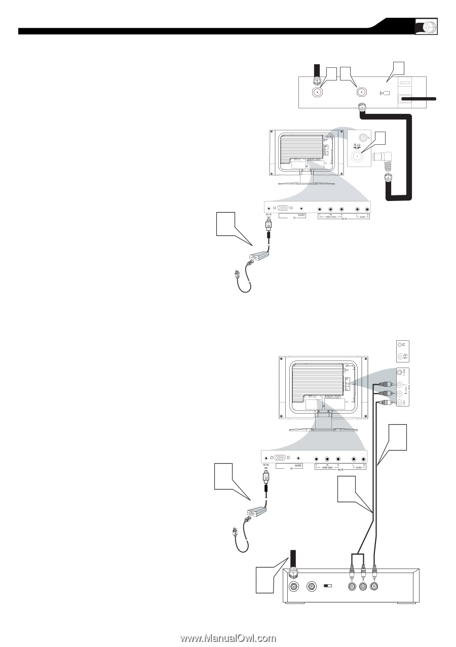
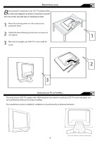
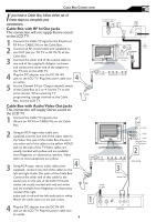
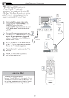
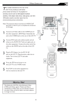
CABLE BOX CONNECTIONS I f you have a Cable Box, follow either set of these steps to complete your connections. Cable Box with RF In/Out Jacks This connection will not supply Stereo sound to the LCD TV. 1 Connect the Cable TV signal to the IN jack (or RF IN or CABLE IN) on the Cable Box. 2 Connect an RF coaxial cable (not supplied) to the OUT jack (or TO TV or RF OUT) of the Cable Box. 3 Connect the other end of the coaxial cable to one end of the supplied L-Adapter as shown, and connect the other end of the adapter to the TV jack on the LCD TV. 4 � Plug the DC adapter into the DC IN 16V jack on the LCD TV. Plug the power cable into an outlet. 5 Set the Channel 3/4 (or Output channel) switch of the Cable Box to 3 or 4. Set the TV to the same channel. When watching TV programming, change channels at the Cable Box, not the LCD TV. Cable Box with Audio/Video Out Jacks This connection will supply Stereo sound to the LCD TV. 1 Connect the Cable TV signal to the IN jack (or RF IN or CABLE IN) on the Cable Box. 2 Using an RCA-type video cable (not supplied) connect one end of the video cable to the Video Out jack of the Cable Box.Connect the other end of the cable to the yellow VIDEO jack on the side of the TV.Video cables are usually marked with yellow and are available from Magnavox or electronics retailers. Video jacks on most equipment are yellow. � Using RCA-type, stereo audio cables (not 3 supplied), connect one end of the cables to the left and right Audio Out jacks of the Cable Box. Connect the other end of that cable to the Audio jack on the side of the LCD TV.Audio cables are usually marked with red and white and are available from Magnavox or electronics retailers.The right audio jack is red and the left audio jack is white. Match the cable colors to the jack colors. 4 Plug the DC adapter into the DC IN 16V jack on the LCD TV. Plug the power cable into an outlet. 9 The Cable TV signal from the Cable Company �� CABLE IN TO TV � OUTPUT CH 3 4 � L-Adapter Side Jack Panel of Television 75 � Coaxial Cable VGA PC DC Adapter Power Cable VGA PC DC Adapter Power Cable Cable TV signal S - VIDEO AUDIO VIDEO Side Jack Panel of Television � Video Cable � Audio Cable � CABLE IN OUTPUT CH 3 4 TO TV L R AUDIO OUT VIDEO OUT Cable Box
-
 1
1 -
2
-
3
-
 4
4 -
 5
5 -
 6
6 -
 7
7 -
 8
8 -
 9
9 -
 10
10 -
 11
11 -
 12
12 -
 13
13 -
 14
14 -
15
-
16
-
17
-
18
-
19
-
20
-
21
-
22
-
23
-
24
-
25
-
26
-
27
-
28
-
29
-
30
-
31
-
32
-
33
-
34
-
35
-
36
-
37
-
38
-
39
 |
 |