Makita AC310H Owners Manual - Page 5
Storage, Installation And Break-in, Procedures - hp air compressor
 |
View all Makita AC310H manuals
Add to My Manuals
Save this manual to your list of manuals |
Page 5 highlights
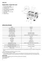
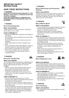
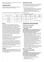
STORAGE Before you store the air compressor, make sure you do the following: 1. Review the "Maintenance" and "Operating Procedures" sections and perform maintenance as necessary. Be sure to drain water from the air tank. 2. Protect the electrical cord and air hose from damage (such as being stepped on or run over). Store the air compressor in a clean and dry location. DESCRIPTION OF OPERATION DRAIN VALVE: The drain valve is located at the bottom of the air tank and is used to drain condensation at the end of each use. THERMAL CIRCUIT BREAKER: The electric motor has a manual reset thermal circuit breaker. If the motor overheats for any reason, the circuit breaker will shut off the motor. Turn pressure switch to the "off" position and wait for unit to cool before pushing the reset button and restarting the compressor. MOTOR THERMAL OVERLOAD PROTECTOR: When the current rating of the motor is exceeded the thermo-protector will open and shut off the motor automatically. The motor must be allowed to cool down before restarting. The compressor will automatically restart after the motor cools down. ON/AUTO - OFF SWITCH: Turn this switch to "on" to provide automatic power to the pressure switch and to "off" to remove power when finished using the compressor or when compressor will be left unattended. AIR INTAKE FILTER: This filter is designed to clean air coming into the compressor pump. This filter must always be clean and free from obstructions. See "Maintenance". AIR COMPRESSOR PUMP: To compress air, the piston moves up and down in the cylinder. On the down stroke, air is drawn in through the air intake valve. The exhaust valve remains closed. On the upstroke of the piston, air is compressed. The intake valve closes and compressed air is forced out through the exhaust valve, through the outlet tube, through the check valve and into the air tank. Useable air is not available until the compressor has raised the air tank pressure above that required at the air outlet. CHECK VALVE: When the air compressor is operating, the check valve is "open", allowing compressed air to enter the air tank. When the air compressor reaches "cut-out" pressure, the check valve "closes", allowing air pressure to remain inside the air tank. PRESSURE SWITCH UNLOADING VALVE: The pressure switch unloading valve located on the side of the pressure switch, is designed to automatically release compressed air from the compressor head and the outlet tube when the air compressor reaches "cut-out" pressure. PRESSURE SWITCH: The pressure switch automatically starts the motor when the air tank pressure drops to the factory set "cut-in" pressure. It stops the motor when the air tank pressure reaches the factory set "cut-out" pressure. SAFETY VALVE: If the pressure switch does not shut off the air compressor at its "cut-out" pressure setting, the safety valve will protect against high pressure by "popping out" at its factory set pressure which is slightly higher than the pressure switch "cut-out" setting. OUTLET PRESSURE GAUGE: The outlet pressure gauge indicates the air pressure available at the outlet side of the regulator. This pressure is controlled by the regulator and is always less or equal to the tank pressure. See "Operating Procedures". TANK PRESSURE GAUGE: The tank pressure gauge indicates the air pressure in the tank. REGULATOR: The air pressure coming from the air tank is controlled by the regulator knob. Turn the knob clockwise to increase pressure and counter-clockwise to decrease pressure. To avoid minor re-adjustment after making a change in pressure setting, always approach the desired pressure from a lower pressure. When reducing from a higher to a lower setting, first reduce to some pressure less than desired pressure. Depending on the air requirements of each particular accessory, the outlet regulated air pressure may have to be adjusted while you are operating the accessory. COMPRESSED AIR OUTLET; "HP" marking For High Pressure Pneumatic Tool Exclusive Use Outlet Max Pressure; 375 PSIG (2.6 MPa) COMPRESSED AIR OUTLET; "RP" marking For Regular Pressure Pneumatic Tool Use Outlet Max Pressure; 130 PSIG (0.9 MPa) INSTALLATION AND BREAK-IN PROCEDURES LOCATION OF THE AIR COMPRESSOR Locate the air compressor in a clean, dry and wellventilated area. The air filter must be kept clear of obstructions, which could reduce air delivery of the air compressor. The air compressor should be located at least 12 inches away from the wall or other obstructions that will interfere with the flow of air. The air compressor head and shroud are designed to allow for proper cooling. If humidity is high, an air filter can be installed on the air outlet adapter to remove excessive moisture. Follow the instructions packaged with the air filter for proper installation. 5
-
 1
1 -
 2
2 -
 3
3 -
 4
4 -
 5
5 -
 6
6 -
 7
7 -
 8
8 -
 9
9 -
 10
10 -
 11
11 -
12
-
13
-
14
-
15
-
16
-
17
-
18
-
19
-
20
-
21
-
22
-
23
-
24
 |
 |
