Makita JN3200 Instruction Manual - Page 4
English - punch
 |
View all Makita JN3200 manuals
Add to My Manuals
Save this manual to your list of manuals |
Page 4 highlights
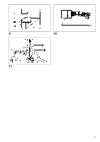
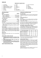
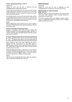
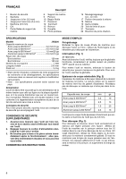
ENGLISH 1 Lock button 2 Switch trigger 3 Gauge for mild steel : 3.2 mm 4 Gauge for stainless : 2.5 mm 5 Mouth (3.5 mm clearance) 6 Wrench 7 Lock nut 8 Die holder Explanation of general view 9 Punch 10 Screw 11 Loosen 12 Cutting edge 13 Groove 14 Pin 15 Punch holder 16 Grind/sharpen; 0.3 - 0.4 mm 17 Remove dull portion 18 Die 19 Washer 20 Limit mark 21 Screwdriver 22 Brush holder cap SPECIFICATIONS Model JN3200 Max. cutting capacities Steel up to 400 N/mm2 3.2 mm/10 ga Steel up to 600 N/mm2 2.5 mm/13 ga Steel up to 800 N/mm2 1.0 mm/20 ga Aluminum up to 200 N/mm2 2.5 mm/13 ga Min. cutting radius Outside edge 128 mm Inside edge 120 mm Strokes per minute 1,300 Overall length 215 mm Net weight 3.4 kg • Due to our continuing program of research and development, the specifications herein are subject to change without notice. • Note: Specifications may differ from country to country. Power supply The tool should be connected only to a power supply of the same voltage as indicated on the nameplate, and can only be operated on single-phase AC supply. They are double-insulated in accordance with European Standard and can, therefore, also be used from sockets without earth wire. Safety hints For your own safety, please refer to the enclosed Safety instructions. ADDITIONAL SAFETY RULES 1. Always be sure that the tool is switched off and unplugged before carrying out any work on the tool. 2. Always lead the power supply cord away from the tool towards the rear. 3. Do not touch the blade or the workpiece immediately after operation; they may be extremely hot and could burn your skin. SAVE THESE INSTRUCTIONS. OPERATING INSTRUCTIONS Pre-lubrication Coat the cutting line with tool oil when cutting mild steel or stainless; use light oil or kerosene when cutting aluminum. Switch action (Fig. 1) CAUTION: Before plugging in the tool, always check to see that the switch trigger actuates properly and returns to the "OFF" position when released. To start the tool, simply pull the trigger. Release the trigger to stop. For continuous operation, pull the trigger and then push in the lock button. To stop the tool from the locked position, pull the trigger fully, then release it. Permissible cutting thickness (Fig. 2) The thickness of material to be cut depends upon the tensile strength of the material itself. The groove on the die holder acts as a thickness gauge. Do not attempt to cut any material which will not fit into this groove. Max.cutting capacities mm ga Steel up to 400 N/mm2 3.2 10 Steel up to 600 N/mm2 2.5 13 Steel up to 800 N/mm2 1.0 20 Aluminum up to 200 N/mm2 2.5 13 This tool can cut any thickness of aluminum plate that fits into the tool's mouth (3.5 mm clearance). Cutting method (Fig. 3) Smooth cutting is achieved by holding the tool upright and applying gentle pressure in the cutting direction. Apply tool oil to the punch about every 10 meters of mild steel or stainless steel to be cut. Light oil or kerosene should be used to keep an aluminum lubricated continuously. Failure to lubricate aluminum in the cut will cause chips to adhere to the tool, dulling the die and punch and increasing load on the motor. Cutouts (Fig. 4) Cutouts can be done by first opening a round hole of about 42 mm diameter or more in the material. 4
-
 1
1 -
 2
2 -
 3
3 -
 4
4 -
 5
5 -
 6
6 -
 7
7 -
 8
8 -
 9
9 -
 10
10 -
11
-
12
-
13
-
14
-
15
-
16
-
17
-
18
-
19
-
20
-
21
-
22
-
23
-
24
-
25
-
26
-
27
-
28
-
29
-
30
-
31
-
32
 |
 |
