©2006
Maytag Services
16026312
3
Important
Information
....................................................
2
Product Design
.............................................................
4
Component Testing
.......................................................
5
Service Procedures
......................................................
10
Service Equipment
.......................................................
10
Drier Replacement
.......................................................
10
Refrigerant Precautions
................................................
11
Line Piercing Valves
.....................................................
11
Open Lines
..................................................................
11
Compressor Operational Test
.......................................
11
Dehydrating Sealed Refrigeration System
....................
12
Leak Testing
.................................................................
12
Testing Systems Containing a
Refrigerant Charge
.................................................
12
Testing Systems Containing
No Refrigerant Charge
............................................
12
Restrictions
..................................................................
13
Symptoms
.............................................................
13
Testing for Restrictions
..........................................
13
Evacuation and Charging
..............................................
14
Evacuation
.............................................................
14
Charging
................................................................
15
Refrigerant Charge
.................................................
15
HFC134a Service Information
.......................................
16
Health, Safety, and Handling
..................................
16
Comparison of CFC12 and HFC134a Properties
.....
16
Replacement Service Compressor
................................
17
Compressor Testing Procedures
............................
17
Brazing
........................................................................
17
Refrigerant Flow
20, 22, 25 cu. ft
.................................
18
Cabinet Air Flow
20, 22, 25 cu. ft
................................
19
20, 22, 25 cu. ft Machine Compartment
Air Flow Diagram
.........................................................
20
Water Dispenser Flow
..................................................
21
Water Flow Schematic
.................................................
22
Typical External Sweat Pattern
...................................
23
Troubleshooting Chart
................................................
24
System Diagnosis
........................................................
27
Disassembly Procedures
Door Removal
Fresh Food Doors
..................................................
30
Freezer Drawer
......................................................
30
Refrigerator Compartment
Upper Light Bulb Cover
..........................................
30
Light Bulb Assembly
..............................................
30
Light Bulb Sockets
................................................
30
Light Switches
.......................................................
30
Fresh Food Thermistor
...........................................
31
Water Tank
............................................................
31
Water Dispenser Facade
.......................................
31
Low Voltage Board
.................................................
31
Chute Extension / Yoke Assembly
.........................
31
Ice Box Compartment
Ice Bin Assembly
...................................................
31
Icemaker Assembly
...............................................
31
Ice Box Fan
...........................................................
31
Auger Motor
...........................................................
31
Solenoid
................................................................
32
Damper
..................................................................
32
Ice Box Thermistor
.................................................
32
Freezer Compartment
Freezer Thermistor
.................................................
32
Light Socket
..........................................................
32
Light Switch
...........................................................
32
Freezer Back Panel
...............................................
33
Evaporator Fan and
Evaporator Motor
...................
33
Defrost Terminator (thermostat)
..............................
33
Defrost Heater
.......................................................
33
Evaporator Removal
...............................................
33
Drawer Assembly
...................................................
34
Drawer Rails
..........................................................
34
Rack and Pinion Gear
............................................
34
Bottom of Cabinet
Front roller assembly
.............................................
34
Rear roller assembly
............................................
34
Machine Compartment
Condenser Fan and Fan motor
...............................
34
Compressor
...........................................................
34
Overload/Relay/Capacitor
.......................................
35
Condensate Drain Pan
...........................................
35
Condensate Drain Tube
..........................................
35
Condenser Removal
...............................................
35
Cabinet Back
High Voltage Board
................................................
35
Control Board (Fully Electronic)
Programming Mode
...............................................
36
Defrost Operation
...................................................
36
Forced Defrost Mode
.............................................
36
Service Test Mode
.................................................
37
Show Room Mode
.................................................
40
Appendix A
Owner’s Manual
........ ........................................
A-1
Table of Contents
 1
1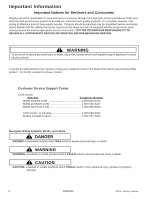 2
2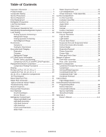 3
3 4
4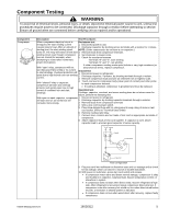 5
5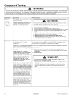 6
6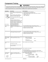 7
7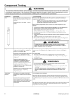 8
8 9
9

