Maytag MFI2266AES Service Manual - Page 4
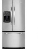
Product Design - refrigerator
 |
View all Maytag MFI2266AES manuals
Add to My Manuals
Save this manual to your list of manuals |
Page 4 highlights
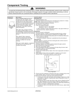
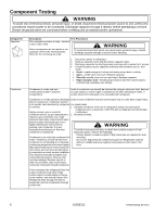
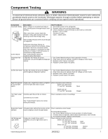
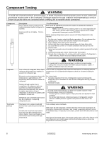
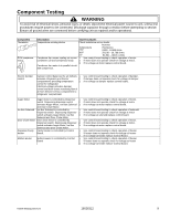
Product Design ! WARNING To avoid risk of electrical shock, personal injury, or death, disconnect electrical power source to unit, unless test procedures require power to be connected. Discharge capacitor through a resistor before attempting to service. Ensure all ground wires are connected before certifying unit as repaired and/or operational. Refrigeration System Compressor forces high temperature vapor into fan cooled tube and wire condenser where vapor is cooled and condensed into high pressure liquid by circulation of air across condenser coil. (See Refrigerant Flow Diagram, page 18) High pressure liquid passes into post-condenser loop which helps to prevent condensation around freezer compartment opening and through molecular sieve drier and into capillary tube. Small inside diameter of capillary offers resistance, decreasing pressure and temperature of liquid discharged into evaporator. Capillary diameter and length is carefully sized for each system. Capillary enters evaporator at top front. Combined liquid and saturated gas flows through front to bottom of coil and into suction line. Aluminium tube evaporator coil is located in freezer compartment where circulating evaporator fan moves air through coil and into fresh food compartment. Large surface of evaporator allows heat to be absorbed from both fresh food and freezer compartments by airflow over evaporator coil causing some of the liquid to evaporate. Temperature of evaporator tubing near end of running cycle may vary from -13°F to -25°F. Saturated gas is drawn off through suction line where superheated gas enters compressor. To raise temperature of gas, suction line is placed in heat exchange with capillary. Defrost System Fully Electronic Defrost System The Control Board adapts the compressor run time between defrosts to achieve optimum defrost intervals by monitoring the length of time the defrost heater is on. After initial power up, defrost interval is 4 hours compressor run time. Defrost occurs immediately after the 4 hours. Note: Once unit is ready to defrost there is a 4 minute wait time prior to the beginning of the defrost cycle. Temperature Controls Freezer compartment temperature is regulated by air sensing thermistor at top front of freezer compartment which actuates compressor. Control should be set to maintain freezer temperature between 0°F to -2°F. Fresh food compartment temperature is regulated by an air damper control governing amount of refrigerated air entering fresh food compartment from freezer. Fresh food compartment temperature should be between 38°F and 40°F. Evaporator and Ice Box Fans are multiple speed low voltage fans that change speeds depending on conditions changing in refrigerator. 4 16026312 ©2006 Maytag Services
-
 1
1 -
 2
2 -
 3
3 -
 4
4 -
 5
5 -
 6
6 -
 7
7 -
 8
8 -
 9
9 -
 10
10 -
11
-
12
-
13
-
14
-
15
-
16
-
17
-
18
-
19
-
20
-
21
-
22
-
23
-
24
-
25
-
26
-
27
-
28
-
29
-
30
-
31
-
32
-
33
-
34
-
35
-
36
-
37
-
38
-
39
-
40
-
41
-
42
-
43
-
44
-
45
-
46
-
47
-
48
-
49
-
50
-
51
-
52
-
53
-
54
-
55
-
56
-
57
-
58
-
59
-
60
-
61
-
62
-
63
-
64
-
65
-
66
-
67
-
68
-
69
-
70
-
71
 |
 |
