Maytag MFI2266AES Service Manual - Page 9
procedures require power to be connected. Discharge capacitor through a resistor before attempting - ice dispenser
 |
View all Maytag MFI2266AES manuals
Add to My Manuals
Save this manual to your list of manuals |
Page 9 highlights
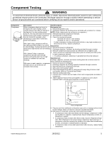
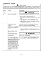
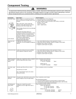
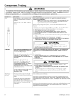
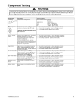
Component Testing ! WARNING To avoid risk of electrical shock, personal injury, or death, disconnect electrical power source to unit, unless test procedures require power to be connected. Discharge capacitor through a resistor before attempting to service. Ensure all ground wires are connected before certifying unit as repaired and/or operational. Component Thermistor ECM condenser motor Description Temperature sensing device Condenser fan moves cooling air across condenser coil and compressor body. Condenser fan motor is in parallel circuit with compressor. Test Procedures Check resistance across leads. Nominal Temperature Resistance 77°F 9,820 - 10182 ohms 36°F 29,198 - 29,788 ohms 0°F 84,561 - 88,011 ohms 1. Use control board testing to check operation of motor. 2. If motor does not operate check for voltage at motor. 3. If no voltage at motor replace control board. Electric damper control Damper control balances the air delivery 1. between refrigerator and freezer 2. compartments providing temperature 3. control for refrigerator. Electrical voltage activates damper control and door closes restricting flow of air from freezer/ ice box compartment to refrigerator compartment. Use control board testing to check operation of damper. If damper does not operate check for voltage at damper. If no voltage at damper replace control board. Auger Motor Auger motor is controlled by Dispenser 1. switch. Depressing dispenser switch 2. activates Auger Motor, Ice Box Solenoid 3. and Door Chute Motor. Ice Box Solenoid Ice Box Solenoid is controlled by 1. Dispenser switch. Depressing dispenser 2. switch activates Auger Motor, Ice Box 3. Solenoid and Door Chute Motor. Door Chute Motor Door chute motor is controlled by 1. Dispenser switch. Depressing dispenser 2. switch activates Auger Motor, Ice Box 3. Solenoid and Door Chute Motor. DispenserCavity Cavity Heater is controlled by Control 1. Heater Board. 2. 3. Mullion Heater Mullion Heater is controlled by Control 1. Board. 2. 3. Use control board testing to check operation of motor. If motor does not operate check for voltage at motor. If no voltage at motor replace control board. Use control board testing to check operation of solenoid. If motor does not operate check for voltage at motor. If no voltage at solenoid replace control board. Use control board testing to check operation of motor. If motor does not operate check for voltage at motor. If no voltage at motor replace control board. Use control board testing to check operation of heater. If heater does not operate check for voltage at heater. If no voltage at heater replace Control Board. Use control board testing to check operation of heater. If heater does not operate check for voltage at heater. If no voltage at heater replace Control Board. ©2006 Maytag Services 16026312 9
-
 1
1 -
2
-
3
-
 4
4 -
 5
5 -
 6
6 -
 7
7 -
 8
8 -
 9
9 -
 10
10 -
 11
11 -
 12
12 -
 13
13 -
 14
14 -
15
-
16
-
17
-
18
-
19
-
20
-
21
-
22
-
23
-
24
-
25
-
26
-
27
-
28
-
29
-
30
-
31
-
32
-
33
-
34
-
35
-
36
-
37
-
38
-
39
-
40
-
41
-
42
-
43
-
44
-
45
-
46
-
47
-
48
-
49
-
50
-
51
-
52
-
53
-
54
-
55
-
56
-
57
-
58
-
59
-
60
-
61
-
62
-
63
-
64
-
65
-
66
-
67
-
68
-
69
-
70
-
71
 |
 |
