McAfee IIP-M65K-ISAA Product Guide - Page 29
Connect the cables for tap mode, Cable the failover interconnection ports, Search the KnowledgeBase
 |
View all McAfee IIP-M65K-ISAA manuals
Add to My Manuals
Save this manual to your list of manuals |
Page 29 highlights
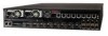
Attaching Cables to the Sensor Connect the cables for tap mode 4 Connect the cables for tap mode To deploy the Sensor in tap mode, you must use a Sensor's Gigabit Ethernet Monitoring port pair with a third-party external tap. For a list of McAfee-approved third party vendors, see the KnowledgeBase at http:// mysupport.mcafee.com/Eservice/. Click the link Search the KnowledgeBase and locate the relevant KnowledgeBase article. Task 1 Plug the cable appropriate for use with your Gigabit Ethernet into one of the Monitoring ports, for example, 1A. 2 Plug another cable into the peer of the port used in Step 1. 3 Connect the other end of each cable to the tap. 4 Connect the network devices that you want to monitor to the tap. See also Cable types for routers, switches, hubs, and PCs on page 28 How to use peer ports on page 27 Connect the cables for SPAN or hub mode For the Sensor, monitoring in SPAN or hub mode occurs in in-line fail-open mode. When you monitor in SPAN or hub mode, you use only single ports. To connect an Sensor to a SPAN port or hub, plug an LC fiber-optic or 45 cable into one of the modules and connect the other end of the cable to the SPAN port or the hub. See also Cable types for routers, switches, hubs, and PCs on page 28 Cable the failover interconnection ports Failover requires connecting two identical M-6050 sensors on the same software version using an interconnection cable. Gigabit ports 4A is the interconnection port on the M-6050. A failover cable is the only additional hardware required to support failover communication between two M-6050 sensors. McAfee® Network Security Platform M-6050 Sensor Product Guide 29
-
 1
1 -
2
-
3
-
4
-
5
-
6
-
7
-
8
-
9
-
10
-
11
-
12
-
13
-
14
-
15
-
16
-
17
-
18
-
19
-
20
-
21
-
22
-
23
-
 24
24 -
 25
25 -
 26
26 -
 27
27 -
 28
28 -
 29
29 -
 30
30 -
 31
31 -
 32
32 -
 33
33 -
 34
34 -
35
-
36
-
37
-
38
 |
 |
