Netgear FE508 Installation Guide - Page 13
Physical Description, Front Panel
 |
UPC - 606449000146
View all Netgear FE508 manuals
Add to My Manuals
Save this manual to your list of manuals |
Page 13 highlights
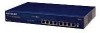
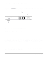
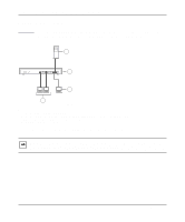
Chapter 2 Physical Description This chapter describes the hardware features of the NETGEAR Model FS508 Fast Ethernet switch. Front Panel For easier management and control of the Model FS508 switch, familiarize yourself with the ports, LEDs, and Normal/Uplink push button on the front panel of the switch, as illustrated in Figure 2-1. 1 2 8 PORT 10/100Mbps Fast Ethernet Switch Power 100 Mbps 1234 5678 Green = Rx/Tx Yellow = Collision 4 5 AUTO 10/100 Mbps MODELFS508 Link 1 FDX 2 3 4 5 6 7 8 Normal/Uplink 3 Key: 1 = Power LED 2 = 100 Mbps LEDs for ports 1 through 8 3 = Rx/Tx and Collision LEDs for ports 1 through 8 4 = 10/100 Mbps ports with Link and FDX LEDs on each port 5 = Normal/Uplink push button to configure port 8 Figure 2-1. Front panel of the Model FS508 switch 690EA Physical Description 2-1
-
 1
1 -
2
-
3
-
4
-
5
-
6
-
7
-
 8
8 -
 9
9 -
 10
10 -
 11
11 -
 12
12 -
 13
13 -
 14
14 -
 15
15 -
 16
16 -
 17
17 -
 18
18 -
19
-
20
-
21
-
22
-
23
-
24
-
25
-
26
-
27
-
28
-
29
-
30
-
31
-
32
-
33
-
34
-
35
-
36
-
37
-
38
-
39
-
40
-
41
-
42
 |
 |